Continue to Site

Eng-Tips is the largest engineering community on the Internet

Intelligent Work Forums for Engineering Professionals

  • Congratulations KootK on being selected by the Eng-Tips community for having the most helpful posts in the forums last week. Way to Go!

Reading Pump Curve 6

Status
Not open for further replies.

resilientsoma

Mechanical
Jul 11, 2012
34
Hello all,
When looking at a pump curve, how do you determine if it's safe to run at a certain GPM without causing harm to the pump internals (seals, bearings, impeller).

For example, FLYGT 3300.181 : CLICK FOR SPECS

If I ran my system at 90 GPM, would this be okay and why (please feed me some basics)? If not, what can be the damage? Anything to recommend or change in the system besides picking a new pump?

Your help is greatly appreciated. I'm a new engineer; hopefully I'll be able to help someone later on!!!
 
Replies continue below

Recommended for you

Attached is a collection of articles and diagrams explaining what you can expect when you try operating off BEP. Generally you need to be within 80 and 105% of BEP for best performance and minimum maintenance. Here's why.

"People will work for you with blood and sweat and tears if they work for what they believe in......" - Simon Sinek
 
 http://files.engineering.com/getfile.aspx?folder=51baa316-d738-4064-9437-4a9fdac1f069&file=pump_op_pt_vs_reliability.zip
BigInch…that's a nice set of articles. Thanks.

resilientsoma…when in doubt, talk to the manufacturer or one of their reps (the good ones are engineers themselves). The pump you reference will NOT be happy at 90 gpm and neither will you or your client. That pump is far too large for 90 gpm.

==========
"Is it the only lesson of history that mankind is unteachable?"
--Winston S. Churchill
 
Burn baby, burn!

"People will work for you with blood and sweat and tears if they work for what they believe in......" - Simon Sinek
 
haha, yeah I had a itch that it wouldn't work with that GPM range. Some of our processes require only 90 GPM, so maybe putting a drain pipe at the header to dump back into the tank will help. Say if you put it up to 250 GPM, water can exit to the tank as well as supply the 90 GPM needed without harm to the pump!


THANKS A LOT everyone, the articles are a great help - NOW I NEED to figure out how to plot the BEP curve for the pump and process requirements. I will have to use your information for this tomorrow!

How were you able to tell by looking at the curve in my link provided that 90 GPM is too little for this pump though? It's a 460V Flygt 60HZ, and kW I believe ranges from 28-51.
 
Less than 20 % BEP gets critical. 10% BEP flow starts cooking up the soup.

"People will work for you with blood and sweat and tears if they work for what they believe in......" - Simon Sinek
 
How were you able to tell by looking at the curve in my link provided that 90 GPM is too little for this pump though? It's a 460V Flygt 60HZ, and kW I believe ranges from 28-51


I'm not sure where that information is available on the chart you attached. When the flows start at 1,000 gpm and go up from there for the various pumps, 90 gpm sounds a little small.

 
I'm not sure where that information is available on the chart you attached. When the flows start at 1,000 gpm and go up from there for the various pumps, 90 gpm sounds a little small

Okay, that makes sense, but just wondering the basics of why; is it because it will dead-head, causing cavitation and become very hot?? If you put a VFD on a pump, can you just turn down the load, protecting the pump to run at lower GPM's than it's designed for?
 
if you read the documents from BigInch, you may find some of your questions will be answered.
 
Question: Why would you want to run this pump at 90 GPM?

It is a capital mistake to theorise before one has data. Insensibly one begins to twist facts to suit theories, instead of theories to suit facts. (Sherlock Holmes - A Scandal in Bohemia.)
 
@ nfinit : I have been reading his articles; I'm not quite done yet, but they are very helpful so far. I'm just trying to stay updated with this thread.

@Artisi : The pump has been in place for many years, and going through a lot of rebuilds, most likely to operating out of its operating curve. 90 GPM is needed for certain process requirements (manufacturing). It isn't always at this GPM range, but sometimes it's required.

I'll am really trying to study this more and try to understand as much as possible before posting things to waste your time; sorry.
 
Install a second smaller pump for the 90GPM duty, probably a lot cheaper in the long-run.

It is a capital mistake to theorise before one has data. Insensibly one begins to twist facts to suit theories, instead of theories to suit facts. (Sherlock Holmes - A Scandal in Bohemia.)
 
@ Artisi : that was thought about for sure. I'm just trying to work with what we have; of course not trying to go through many rebuilds as we do now though. We do have VFD for the pumps, but are VFD's a good solution for pump protection... for low GPM, turn setpoint % down from the 60Hz ... still trying to look into this/
 
You could easily have problems with the motor running at that slow a speed as well.

1.) Motors lose a heck of a lot efficiency when they are at less than 50% load.
2.) Motors must have special windings to use a VFD. A VFD on a motor not suitable for VFD service could easily overheat and burn.
3.) A new motor suitable for this service will be a major, major cost item.
4.) If you can afford that option, then you can EASILY afford a new special purpose pump for 90 gpm.

To put it bluntly, don't be dumb about this. You are a new engineer. There's far too much to say about this subject than we have time to teach you on the internet. Please listen to Artisi. Take and make his advice work to your advantage. Don't be stubborn. Buy another pump for those times you need 90 gpm!

"People will work for you with blood and sweat and tears if they work for what they believe in......" - Simon Sinek
 
@ BigInch :
There already is a VFD for our pump, but we currently do not use it, only a set-point can be used, but is maintained at close to 95% of its 60 HZ. We have PLC control, just need to make it automatic w/ PID integration. I know there are certain concerns w/ running a VFD from your articles, but these pumps can handle it for the most part.

My main concern is the low GPM obviously, so a working VFD and/or a system bypass is necessary - bingo.

My other concern is just understanding the simple basics of what happens when the head is at MIN and what happens when the head is at MAX on the pump curve vs GPM.

I'm not trying to be dumb, just trying to see if I can get some expert opinions and input, which I have. I want to keep an open mind and try to learn everything I can. Someday I will be more experienced and can help the next struggling new engineer. I have many areas I work in; so please excuse me.

Thanks again.


That's quite a different set up than what you mentioned on 9 Oct.

But it still doesn't matter that much. With a VFD running the pump at 10% BEP, you've still got the efficiency degrade of both the motor and the VFD, each running at 10% of their rated load.
You might be able to do it, if the motor is rated for VFD service, but you'll still pay for it, bypass or not. At 10% of BEP, probably both the VFD and motor will have about the same 10% efficiency, giving a subtotal net 5% eff and you still have the pump efficiency to multiply so, say 0.65 or so for that. Hey, that's about 3% net efficiency x 0.9 or so for power line loss, maybe you'll get 2.5% out of it. You might be able to do it, but I wouldn't even want to do that during emergency upset conditions. The equipment might work, but you won't be able to pay for it.

Are we getting any closer to solving this your way?
Artisi's solution still looks pretty damned good to me.
You can't fool Mother Nature!

"People will work for you with blood and sweat and tears if they work for what they believe in......" - Simon Sinek
 
At a flow of 90GPM - do you know what the discharge head is? The pump speed will change as the square of the speed change - reducing the speed to get your 90GPM - (without spending the time to calculate it) the head developed will probably be only a few metres.
A good exercise for you to calculate the new system curve and pump curve at the reduced speed / flow.

It is a capital mistake to theorise before one has data. Insensibly one begins to twist facts to suit theories, instead of theories to suit facts. (Sherlock Holmes - A Scandal in Bohemia.)
 
Or instead of calculating it, estimate and just draw a small circle around (0,0).

"People will work for you with blood and sweat and tears if they work for what they believe in......" - Simon Sinek
 
@ BigInch & Artisi :

From more researching and getting your inputs, I'm getting to where I need to be even more. The efficiency w/ VFD control does seem problematic. Our pumps are rated for VFD's so that is what I will look into more. I can understand your explanations and will keep this in mind. I will try to talk my team into a smaller pump for these low GPM conditions. So the discharge head can be assumed to be around zero (0) at 90 GPM, based on looking at the curve.

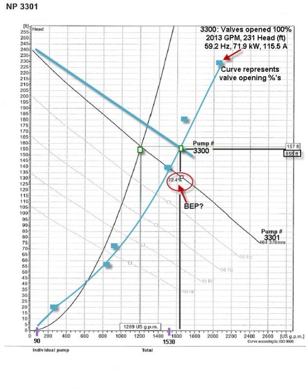
I did some measurements with our setup; running from 90 GPM to 1530 GPM (blue line). The two curves 3300, 3301 represent different model pump curves. How would you determine the BEP, or as you said before, would you have to get this from the vendor? Anything else suspicious w/ my findings that you can see? It looks like the pump will be happy at 1200 GPM w/ Pump 3301 and 1650 GPM with Pump 3300. So how do you base your BEP off of that? I really do appreciate your time and efforts. The 72.4% is for Pump 3301, which I got from the pump curve. I assume that is the EFF at the BEP?

7A0BA3DC-8235-4ACB-9EA3-B8197E97EF12-2040-000004972DEA102D.jpg
 
BEP is found at the flat spot on the power curve. I've marked approximate bep for 4 of the pumps on the data you've given above. see attch. You can measure power at varying flowrates while holding the same rpm, then connect the dots.
Change the speed to a new rpm and measure again.

The bep should, more or less, show a direct relationship to speed as you as you move from rpm to rpm. If the bep flow is 1600 gpm at full rated speed, it will be around 800 gpm at half rated speed. Head at half speed will be (1/2)^2 = 1/4[sub]th[/sub] that of the head at rated speed.

Pump efficiency stays roughly the same for all BEP points for each rpm. In other words, if your blue line intersection with the pump curve at rated speed is indeed BEP, then the BEP point at each pump speed would follow the blue line as you changed rpm. The same pump efficiency at rated speed would then be used at the BEP point for each rpm.

Motor efficiency drops with load.
I usually assume two straight lines
(0% load,0% eff) to (50% load, 75% eff)
(50% load, 75% eff) to (Max Eff, 100% load)

Don't forget VFD efficiency drops with load too.

Calculate the power cost at 10% motor eff and 10% VFD eff and 65% pump eff and 90% power line efficiency. $/gallon pumped will be quite high. That should force the team to consider buying a secondary pump for small flows. The more time you spend at 10% flow, the more money it will cost.

"People will work for you with blood and sweat and tears if they work for what they believe in......" - Simon Sinek
 
 http://files.engineering.com/getfile.aspx?folder=e1390372-875e-4e4e-b5a7-bbac67dde5f2&file=c3300181.pdf
Status
Not open for further replies.

Part and Inventory Search

Sponsor