Eng-Tips is the largest engineering community on the Internet

Intelligent Work Forums for Engineering Professionals

  • Congratulations waross on being selected by the Tek-Tips community for having the most helpful posts in the forums last week. Way to Go!

CSV vs. VFD Discussion, Am I missing something? 2

Status
Not open for further replies.

ibosley

Mechanical
May 1, 2015
6
0
0
US
I've poked around on this forum and have noticed this has come up before. I was referred to this page by a gentleman named Cary at a cycle stop valve website. We have had discussions, if you could call it that, regarding the operating costs of CSVs vs. VFDs. I made some points from an engineering perspective, notified Cary of my credentials so that he didn't think I was just some internet troll, and even provided him with calculations showing the case study he sent me proves my point. My original point/premise was that CSVs are not ideal for controlling flow in most applications when compared to VFDs. After several exchanges I presented my results to Cary based on parameters that he defined with the following results:

1) Cary changed his premise from CSVs save energy compared to VFDs to VFDs are not 100% efficient therefore they waste energy.
2) No input was given regarding my calculations, there was not flaw found with them. Cary simply refers to them as "magic."
3) He still insists that I am closed minded and do not get it.

He says you guys would be able to help me understand how his product is superior to VFDs, since he keeps referencing several unknown engineers who agree with him. I would question the credentials of said engineers but am open to discussion if I am missing something here.

Normally I would not engage in a shouting match over something so trivial, but he has admitted several times in emails that he has installed thousands of these devices. I have admitted to him they have their appropriate uses, but throttling a pump from 225 gpm to 10 gpm is not one of them. He is costing his customers a lot of money in operating costs, so much that the maintenance cost savings surely do not justify them. This is an issue because he claims to remove/retrofit existing VFD systems to incorporate his product.

The attached case study was provided based on Cary's input for the following type of system:

A well pump feeding a variable flow irrigation system with a fairly consistent head. Dynamic losses at 225 gpm are equal to 9' but are negligible at significantly lower flows for the pipe diameters presented. The required head at the minimum flow of 10 gpm is 295'. The required head at 225 gpm is 315'. 115' of that head is a result of the manifold at ground level needing to be at 50 psi regardless of flow for the branch circuit sprinklers to work.

Cary graciously provided a pump curve for a Grundfos 230S250-7 well pump with a presumed VFD driver. He noted the power at 10 GPM and 450' of head to be 14 HP. Obviously the curves don't go down this far so I manually calculate an 8% efficiency from this information. I assume this same efficiency when calculating the same thing as if the pump had slowed to a lower speed to hit the 295' of head at 10 GPM and came up with a 9.8 BHP rating for the driver. It is important to note we are calculating what is going on across the pump and not across the pump and discharge of the CSV, I think this may be the source of Cary's misunderstanding. His CSV induces an artificial head pressure to back the presumed single speed pump on its curve in order to make it hit 10 gpm.

After all of this was delivered to Cary he switched arguments to say the VFD uses 900% more than the theoretical WHP of 0.8 HP and therefore VFDs do not save energy (he will not accept that pumps are rated on efficiency and not as a percent above nominal). My premise was the VFD saves energy compared to the CSV because you aren't pumping across an induced head pressure from a throttling device. The trivial calculation shows 14 HP is clearly greater than 9.8. This is only at minimum flow of course, and I only presented energy calculations at this point versus integrating under the shaded part of the pump curve that denotes wasted throttling energy and dividing by the average efficiency. That number would drive these financials much higher. I was being very conservative in my analysis regarding energy.

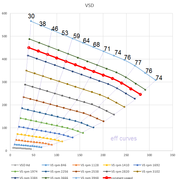
Of course, if you note the two green lines on the pump curve with the shaded area you'll note that a VFD is highly inappropriate for this application anyway. I tried to demonstrate this by drawing an example of a system curve with more dynamic losses that shot through the BEP region of the proposed pump. That was immediately compared to the given example and dismissed, but I attempted to demonstrate what a system curve would look like for that pump (if it were sized and specified correctly). The typical system curve I drew is more appropriate for this type of pump, as the RPM drops and follows the affinity laws in this region (constant efficiency).

My proposed solution was to use a well pump with a smaller diameter and a booster pump at ground level with a VFD to maintain constant manifold pressure at 50 psi. If you follow the curves it is a lot more appropriate to do this versus make the pump operate in the 8% efficiency region for prolonged periods of time, otherwise you are throwing kWhs out the window.

I've tried to be as neutral as possible while writing this regarding Cary's comments. I'm sure I've slanted in my favor inadvertently. He says he is going to post the whole thread on his website, if he does so I will share here as well but otherwise I like to keep conversations confidential. I'm only here on his recommendation. I'm looking for another mechanical PE to set me straight on this issue, if it can be done. Thank you for your time and I'm looking forward to the discussion.
 
 http://files.engineering.com/getfile.aspx?folder=8888c16f-4ef6-43af-a726-7340bafb3fc8&file=Well_Pump_Comments.xps
Replies continue below

Recommended for you

Yeah I read most of that forum but no one sat down and did the math. I want someone to review my theory and notes for accuracy. From where I am standing right now there is no conceivable way you can claim a CSV throttling device saves money compared to a VFD, even when the VFD is grossly inappropriate for the given application as listed above.
 
I think the point is:

The vaule of VFD depends on your system. EG: If the static dP is a large part of your total dP the VFD wont be as effective (your reduction in speed would not be as great to reduce the flow rate by a given fraction). System where VFD could be valuable would e.g. be heating circulations where its a closed circuit and elevations (from an energy point of view) does not matter. This is why e.g. Grundfos sells many small VFD pumps. Its also easy to build a generalised control loop that will ensure fairly good performance in a "general" system. Also in Europe where energy is more expensive VFD tends to become economical with a smaller svaings in %.

I tried to create a "generalised" example showing two different system curves one with no static head and one with a static head but apart from that similar and the a nominal speed and a 90% speed.

As you can see if you open the file the one with the static head will drop to almost 0% flow where the one with no statis head will be about half.

Best regards, Morten


 http://files.engineering.com/getfile.aspx?folder=388fc935-adad-4adc-80b4-3aa9f9b7fb70&file=vfd_pump_curve.pdf
Stopped reading halfway through when you said 10gpm at reduced speed, with 295' of head. It doesn't work that way, head decreases to the rpm^2 (see pump affinity laws.) The reality is, you can't operate most systems at reduced pump speeds like that because the head (rpm^2) drops off much quicker than flow (1:1 ratio to rpm.)
 
Morten,

Thanks for the reply and the graphs. I think we are in agreement regarding using a VFD for a high static head system, it isn't the correct device for the job. Would you also agree with the document in the OP demonstrating how a throttling device over that same domain wastes more money than an (incorrectly sized and installed VFD) for the same job? I illustrated this by shading the area between the pump curve and system curve. The throttling device (CSV) is for a constant speed application.

1gibson,

Please see the attachment in the OP, the pump head at full speed is 450', not 315'. Otherwise I would agree with you. The point I'm trying to get clarification on is it is still better to have a VFD installed in this application versus choking the flow with a throttling device from an energy perspective. This is considering the fact the VFD is incorrect for that application anyway. I have had a self described expert tell me the CSV saves money verus the VFD because the VFD uses "900% more power" than the ideal 1 HP it should take at this state point. This is despite the fact the CSC loads the driver at 14 BHP versus around 9.8 BHP for the VFD.

I'm trying to make sure 14 is greater than 9.8 and I'm not taking crazy pills.
 
Took a look at the attachment. This all appears to be operating below minimum flow, so energy costs are going to be negligible compared to repairs that are not covered by the pump warranty. I'm honestly just not interested at that point.

The answer is that you can't really do either one of these things for very long, so it's like arguing about fuel economy while you're driving off of a cliff.
 
Your understanding seems to be the same as mine. Control valves (at least the conventional type) tend to save more energy than VSDs do when operating between 85 and 115% of BEP flow rate. If you operate a substantial portion of the time at 40-60% BEP flow, you might try putting in two identical parallel pumps as an alternative to VDS, but for a system this small, that probably wouldn't make sense. Between 60-85%, VSD is likely to save more than a control valve, but you might have picked your system design operating flow rate badly. Try to reduce it and use a CV. Less than 50%, VSD will save more, as long as they can generate the head you need, but savings drop due to additional inefficiencies introduced by operating motors and VSD at less than 50% load.

The 230S250-7 (25HP) pump curves at various VSD speeds and efficiencies (theoretically) should look something like this,
heads_at_vsd_speeds_msdqnb.png


OMG%20something%20else.png
 
That was the issue I took with the information presented as well, the comparison was made at an operating point that shouldn't exist in the first place. He then goes on to say this is business as usual for him, choking pumps to operate at a point far below minimum flow.

He was obviously trying to catch a VFD in a worse case scenario in order to make his product/method seem to be the superior solution, but even at this point it is not as effective as slowing the speed down to accomplish the same head. It is actually right there on the curve when you calculate the water horsepower and doesn't require calculation to determine. I agree with the assessment neither case is ideal, as I state in an email to him and shared in the OP. I just wanted to get a second opinion regarding the energy consumed by each method.

My proposed solution was a smaller well pump to provide adequate NPSH to a booster pump located at ground level to supply the 50 psi manifold pressure required. Obviously parallel pumps would be even better but you only have room for one in the well I would imagine.

This guy is practicing engineering without a fundamental understanding of physics or any formal education or licensing. He admitted to replacing several VFDs with throttling valves, a severe regression in pumping technology in my opinion. This costs his customers excessive amounts of money in utility payments over the life of the installation when you consider the area of the curve where it throttles flow. This has become more of an ethics issue to me more than anything. If you are going to exert authority on a subject in order to sell a product you better know how that product works and what it does. He seems to pick and choose numbers at random without understanding of how they are related regarding pumping applications.

He still refuses to acknowledge his valve causes the pump to use significantly more power than a VFD for this particular application, even though my calculations and the pump vendor's calculations proving this. This would be fine except his website absolutely slams VFD technology as being less efficient and inappropriate compared to his 100+ year old throttling technology.

Regarding warranty/reliability. He claims they choke flow into the 8% region all the time without issue. Well I would argue the issue is it is operating at 8% efficiency if anything, or in his words "uses 1,200% more power".
 
I think where you need to be careful here is that the VFD will not generate enough head to pump to the surface when below a certain speed. If low head occurs below the flow rate you need to supply, it will work. I assume this is why you need a booster at the surface (?) You will be likely to lose efficiency at the surface if flow to the booster is not close to its BEP, but the head you need there may be so small that you will not be using much power no matter what flow rate you have at any given time.

"replacing several VFDs with throttling valves, a severe regression in pumping technology "
That is far from the case. As a rule of thumb CVs will typically use less energy than a VFD within the range of limits I mentioned above.
VFDs can bring along a host of other problems, any of which could be reasons in themselves to avoid them. With this small system, even if the VFDs ran completely amuck, you could still afford to fix it.

In many cases VFDs can be avoided by robust system design. A system with no variation in flow, use a pump and no valve. With 3 pumps and a control valve you can get a very good range of flow rates all with good efficiencies. With 4 pumps and CVs you can often do better than with VFD and have a reasonably fine control of flow. If you need 3 or 4 pumps for reliability, then why use a VFD at all? If you can combine that with the ability to switch the system on or off, as most irrigation systems can, I would probably not go to VFDs. Nothing is more efficient than a pump alone; no valve, no VFD. KISS is one of the golden principals of engineering.

OMG%20something%20else.png
 
I agree with everything you are saying. VFDs are not a band aide to engineering, but they are useful if used properly just as control valves are useful if implemented properly.

Please tell me if you agree or disagree to the following statement:

"When the flow is reduced, the amps drawn by a pump controlled by a VFD, and a pump controlled by a CSV are almost the same. The difference is that a VFD creates a smaller motor from a larger one, and a CSV de-rates the motor load.

When a VFD slows down a 10 HP motor, until it is only drawing a 5 HP load, it has ?created? a 5 HP motor from the 10 HP. Even though the motor is only drawing half of a 10 HP load, the harmonic content produced by the VFD increases heat in the motor. The motor must be cooled as if it were a fully loaded 5 HP, which still requires ? a foot per second flow. According to the submersible motor cooling chart, a 6" motor in an 8" casing needs a minimum of 45 GPM to remain cool. So a 10 HP pump and motor in 8? casing, cannot be slowed to less than 45 GPM, or the motor will overheat and be destroyed.

The same 10 HP motor controlled by a CSV doesn't need as much flow to remain cool. This is because the 10 HP motor has been ?de-rated? to a 5 HP load. When a CSV restricts a 10 HP pump, the amps can also drop to a 5 HP load. However, the motor is still spinning at 3450 RPM, and is still running on pure sinusoidal AC power, which has no harmonic content. De-rating is described in the chart for motors used in hot water applications. De-rating means a 10 HP motor that is only pulling a 5 HP load, can function properly in water up to 140 degrees. If de-rating a motor means it can remain cool in water up to 140 degrees, then it would take very little flow of 86 degree or cooler water to prevent overheating. This has been tested extensively, and we have found that 5 GPM flow is more than adequate to cool most de-rated motors. The example pump controlled with a VFD can only vary the flow from 100 GPM to 45 GPM. The same pump controlled with a CSV can safely vary the flow from 100 GPM all the way down to 5 GPM.

A smaller 30 GPM pump de-rated with a CSV, can safely vary the flow from 30 GPM all the way down to 1 GPM. This same 4? motor in 5? casing controlled with a VFD, can only reduce the flow from 30 GPM to 7 GPM. "
 
It contains a mixture of fact and pseudo-science. I'm dashing to work and can't answer in full but might get a chance later on.

FWIW I agree that VFD's are useful in many applications, but VFD manufacturers have over-sold them in other applications where they fail to deliver on their promises. In the latter case I'm not surprised they have a bad reputation. I've been arguing on and off for years not to install them on boiler feedwater applications except in very specific circumstances which never seem occur in the real world.
 
"When the flow is reduced, the amps drawn by a pump controlled by a VFD, and a pump controlled by a CSV are almost the same. The difference is that a VFD creates a smaller motor from a larger one, and a CSV de-rates the motor load.

NOT Agreeing. Considering the 230S250-7 (25HP) pump If flow decreased to 220 gpm and your system curve called for 157ft of head, with a VSD you could reduce speed to 2820. VSD power would be around 12HP, constant speed pump would use about 24 HP, so amps would be around 1/2 using a VFD.

When a VFD slows down a 10 HP motor, until it is only drawing a 5 HP load, it has ?created? a 5 HP motor from the 10 HP. Even though the motor is only drawing half of a 10 HP load, the harmonic content produced by the VFD increases heat in the motor. The motor must be cooled as if it were a fully loaded 5 HP, which still requires ? a foot per second flow. According to the submersible motor cooling chart, a 6" motor in an 8" casing needs a minimum of 45 GPM to remain cool. So a 10 HP pump and motor in 8? casing, cannot be slowed to less than 45 GPM, or the motor will overheat and be destroyed.


No. The heat generated from a VFD outputting 5HP to the pump will be converted to both hydraulic power and heat. Say the pump's efficiency with VFD at the flowrate requiring a brake horsepower of 5HP delivered to the pump is 63%. Hydraulic power delivered to the pump will be 5HP * 0.63. Maximum heat generated will be roughly whatever remains = 5* (1-0.63) = 5 * 0.37 * 0.745 kW/HP = 1.38 kW

I assume you mean slowing motor speed to deliver lower flow, not slowing flow rate at constant speed.

If that flowrate was the minimum flowrate, you can see it would heat up to a temperature that would correspond to a heat input of only 1.37 kW, whereas the constant speed 10HP pump would heat up flow to whatever the 10HP * (1-eff) * 0.745 would do. Say efficiency at near shutoff was 0.3, that would be 10 * (1-0.3) * 0.745 = 5.2 kW heating up that minimum flow. 3.8 x the heat of a VFD. Keep in mind that the VFD itself will need extra cooling due to its own increased inefficiency when running at reduced load, as will the motor as loads go below 50% of their respective ratings.


The same 10 HP motor controlled by a CSV doesn't need as much flow to remain cool. This is because the 10 HP motor has been ?de-rated? to a 5 HP load.


No. The opposite. This is more true for VFD controlled motor.

When a CSV restricts a 10 HP pump, the amps can also drop to a 5 HP load.

No. Amps will drop, but at a typically poorer efficiency than a VFD, power will not drop all the way to 5HP.

However, the motor is still spinning at 3450 RPM, and is still running on pure sinusoidal AC power, which has no harmonic content.


Harmonic content creates other types of problems.

De-rating is described in the chart for motors used in hot water applications. De-rating means a 10 HP motor that is only pulling a 5 HP load, can function properly in water up to 140 degrees. If de-rating a motor means it can remain cool in water up to 140 degrees, then it would take very little flow of 86 degree or cooler water to prevent overheating.

Nothing is being derated, it is being unloaded from max rated load. With less power required, there is less capacity to generate heat, but the power used will normally be at lower efficiency, so a greater % of that lesser load will be diverted to creation of heat.

This has been tested extensively, and we have found that 5 GPM flow is more than adequate to cool most de-rated motors.

Most likely true, as only 20% of a pump's rated flow rate will normally keep a motor useably cool.

The example pump controlled with a VFD can only vary the flow from 100 GPM to 45 GPM. The same pump controlled with a CSV can safely vary the flow from 100 GPM all the way down to 5 GPM.

No. A CV controlled pump is typically using higher power at lower flows as in the example above, so safe minimum flows are going to be no lower than around 20% of rated pump flow. A VFD could theoretically reach much lower safe flows, due to its reduced power consumption and generally higher efficiencies at reduced flows, provided it can still generate the head needed to force those minimum flows through the system curve.


"When the flow is reduced, the amps drawn by a pump controlled by a VFD, and a pump controlled by a CSV are almost the same. The difference is that a VFD creates a smaller motor from a larger one, and a CSV de-rates the motor load.

NOT Agreeing. Considering the 230S250-7 (25HP) pump If flow decreased to 220 gpm and your system curve called for 157ft of head, with a VSD you could reduce speed to 2820. VSD power would be around 12HP, constant speed pump would use about 24 HP, so amps would be around 1/2 using a VFD.

Treat the VFD and motor as a functional unit. As an end user you don't give a damn about the motor current, you're interested in the current you're putting in to the VFD because that's what you are paying for. You'll probably find the current is actually slightly less than half because the VFD supplies the motor magnetising current and the VFD has a near-unity displacement power factor. Those with an active front end have a virtually perfect power factor.


When a VFD slows down a 10 HP motor, until it is only drawing a 5 HP load, it has ?created? a 5 HP motor from the 10 HP. Even though the motor is only drawing half of a 10 HP load, the harmonic content produced by the VFD increases heat in the motor. The motor must be cooled as if it were a fully loaded 5 HP, which still requires ? a foot per second flow. According to the submersible motor cooling chart, a 6" motor in an 8" casing needs a minimum of 45 GPM to remain cool. So a 10 HP pump and motor in 8? casing, cannot be slowed to less than 45 GPM, or the motor will overheat and be destroyed.

No. The heat generated from a VFD outputting 5HP to the pump will be converted to both hydraulic power and heat. Say the pump's efficiency with VFD at the flowrate requiring a brake horsepower of 5HP delivered to the pump is 63%. Hydraulic power delivered to the pump will be 5HP * 0.63. Maximum heat generated will be roughly whatever remains = 5* (1-0.63) = 5 * 0.37 * 0.745 kW/HP = 1.38 kW

I assume you mean slowing motor speed to deliver lower flow, not slowing flow rate at constant speed.

If that flowrate was the minimum flowrate, you can see it would heat up to a temperature that would correspond to a heat input of only 1.37 kW, whereas the constant speed 10HP pump would heat up flow to whatever the 10HP * (1-eff) * 0.745 would do. Say efficiency at near shutoff was 0.3, that would be 10 * (1-0.3) * 0.745 = 5.2 kW heating up that minimum flow. 3.8 x the heat of a VFD. Keep in mind that the VFD itself will need extra cooling due to its own increased inefficiency when running at reduced load, as will the motor as loads go below 50% of their respective ratings.

Most modern VFDs don't produce massive harmonics, not like the very old quasi-square drives from the 1970's. And a big motor will almost always get rid of heat more effectively than a small one.


The same 10 HP motor controlled by a CSV doesn't need as much flow to remain cool. This is because the 10 HP motor has been ?de-rated? to a 5 HP load.

No. The opposite. This is more true for VFD controlled motor.

Agree. A 10HP motor dumping 5HP worth of output into a CSV is still doing 10HP work. It gets just as hot as when it is doing 10HP of useful work.


When a CSV restricts a 10 HP pump, the amps can also drop to a 5 HP load.

No. Amps will drop, but at a typically poorer efficiency than a VFD, power will not drop all the way to 5HP.

Agree. And don't forget that magnetising current of a 10HP motor won't reduce, so line current may not reduce all that much, even when it is doing next to no useful work. It will likely draw about 60% of full load current, at a low power factor. Bear in mind low power factor is generally considered a bad thing.


However, the motor is still spinning at 3450 RPM, and is still running on pure sinusoidal AC power, which has no harmonic content.

Harmonic content creates other types of problems.

Modern VFDs aren't that bad for harmonics in the motor. Switching pulses, yes, but not harmonics. And an AFE type will be nice and friendly on the input side too. In fact it will behave like a big resistor.


De-rating is described in the chart for motors used in hot water applications. De-rating means a 10 HP motor that is only pulling a 5 HP load, can function properly in water up to 140 degrees. If de-rating a motor means it can remain cool in water up to 140 degrees, then it would take very little flow of 86 degree or cooler water to prevent overheating.

Nothing is being derated, it is being unloaded from max rated load. With less power required, there is less capacity to generate heat, but the power used will normally be at lower efficiency, so a greater % of that lesser load will be diverted to creation of heat.

Thermal de-rating for a motor in a hot environment? Sure. Wring a bit more out of a motor in a cold environment? Sure.


This has been tested extensively, and we have found that 5 GPM flow is more than adequate to cool most de-rated motors.

Most likely true, as only 20% of a pump's rated flow rate will normally keep a motor useably cool.

The statement is meaningless without context. It's the kind of painfully dumb statement that makes me despair of marketing people. 'Extensively tested' by whom, and on what? I can find plenty motors which would be very upset with only 5gpm of coolant flow. Most of them are quite large motors...


The example pump controlled with a VFD can only vary the flow from 100 GPM to 45 GPM. The same pump controlled with a CSV can safely vary the flow from 100 GPM all the way down to 5 GPM.

No. A CV controlled pump is typically using higher power at lower flows as in the example above, so safe minimum flows are going to be no lower than around 20% of rated pump flow. A VFD could theoretically reach much lower safe flows, due to its reduced power consumption and generally higher efficiencies at reduced flows, provided it can still generate the head needed to force those minimum flows through the system curve.

As you said.
 
Scotty,
I read your responses as carefully as I could and as near as I can gather we agree (pretty closely) on all points, although I thought harmonics might be slightly more of a pain. I certainly won't argue with you about that. Thanks.
 
I concur with everything said, probably because the three of us are engineers or at least have a strong technical background.

This guys website is absolutely littered with this type of misinformation (that is where I found the statement I posted). We've had a rather long email exchange where he basically says I'm wrong without telling my why I am wrong. He admits to not being an engineer, not that he had to.

The attachment in the OP graphically demonstrates what is happening in the system he proposed. The problem is he probably sent that information over thinking it was a shining example of why you definitely want to use a CSV vs VFD in that application. My response was you should use neither, but that the VFD is still more efficient. Most of the information on his site may have been somewhat correct 20-30 years ago but doesn't have any relevance to modern technology or practice.

My proposed method was a smaller single speed pump in the well, as marked on the pump curve chart, with a smaller VFD unit up top to meet the 50 psi requirement. This would allow both pumps to operate closer to BEP.

Please look at his website, if anything to understand why I'm so flustered with it as an engineer. It is cycle stop valves dot com. I am surprised he would direct me to a forum full of engineers who would agree with me, so there must be an ace up his sleeve somewhere I'm unaware of. Regardless, I don't think you could make the numbers agree with what he is doing in almost 100% of the cases where he things they should. Thanks for the input fellas.
 
I know of it. I think that CSV valves are a good way to try to control transient overpressures. I think they may be beneficial in acting as a control valve to hold flow to a certain pressure. I think that they might be better than a VFD within the ranges I mentioned above. Other than that ... I'd have to see the proposed application before I say yea, or nay.
 
Status
Not open for further replies.
Back
Top