Continue to Site

Eng-Tips is the largest engineering community on the Internet

Intelligent Work Forums for Engineering Professionals

  • Congratulations waross on being selected by the Eng-Tips community for having the most helpful posts in the forums last week. Way to Go!

Segmental Tunnel

Status
Not open for further replies.

ForrestCam

Civil/Environmental
Aug 20, 2015
4
Hi all, I am doing research on the construction method of laying 900mm and 600mm pipe underground by segmental tunnel (maybe referred to hand dig tunnel) which is 2m x 2m x 30m tunnel at 6m depth (invert level). could you let me have your view on which main components should be considered when designing the tunnel? any reference could be made to? grade I rock stratum is encountered at the depth of 2m.
 
Replies continue below

Recommended for you

The type of pipe and method of installation would depend on the purpose of the installation. Is this a water pipe, sewer pipe, or electrical installation? What is the terrain, are you close to a stream, or in an urban area?

Refer to the following links:

ftp://ftp.odot.state.or.us/techserv/geo-environmental/Hydraulics/Hydraulics%20Manual/Chapter_16/Chapter_16.pdf

 
I know the word rock means different things to different people , and I don't know what the civil / environmental definition of grade 1 rock is , but as a miner, I would NEVER ask men to hand dig thru rock. Are you prepared to be willing to work alongside the guys doing this excavation?? If not , be very carefull how you write the specifications.
 
Are you talking cut and cover construction?
 
hi bimr, thanks for the reference provided. The purpose of installation is for water pipe by segmental tunnel approach in urban area. Because of site constraints caused by traffic condition and congested underground installations, trench in phase is impossible to launch. Thus the segmental tunnel approach is introduced while the space allowed for launching/receiving pit construction is very limited, i.e. 2.5m(w) x 2.4m(L).

to miningman, your concern is understood. given to the above mentioned situation,there is no alternative but hand dug tunnel is likely.

to buggar, cut and cover construction is unlikely due to the site constraint of my concern.

Therefore, I want to make reference to the past experience for drafting my research and to ask what should I have to care about on the design before carrying out the tunnel works. for instance, where are the loadings applied? what is the appropriate safety factor that should be applied?

please let me have all your views. thanks
 
Forget hand digging. Focus your research on directional drilling and similar technologies.
 
The space allowed for launching/receiving pits would have to substantially larger than 2.5m(w) x 2.4m(L) no matter what technique that you are using.

[ul]
[li]Directional drilling generally does not work in an urban area where it is desired to install the pipe level. You would have too much setback where the pipe enters the ground.[/li]
[li]Pits as deep as 6 m would require substantial shoring.[/li]
[li]The pipes are generally not installed in a tunnel.[/li]
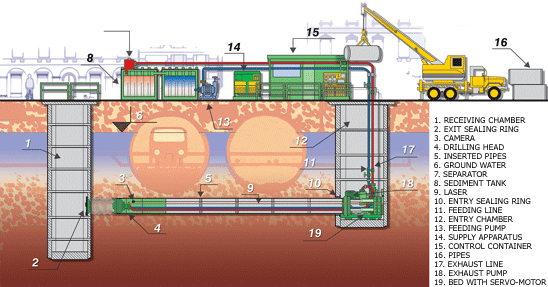
[li]The size of the pipe that you are talking about is also too small for use with a microtunneling machine.[/li]
[/ul]
Mikrotuneling_2D_eourh0.gif


One of the problems that you will encounter is how to make the connection for the service drop for each individual water user. You will have to install another pit to make the connection.

If you are really in the middle of a major city, you would be looking at some type of auger or jacking.
 
hi all, thanks for the fruitful hints. finally, much grateful if you could let me have your view again on how to check the stability of the tunnel formed by 2000mm steel casing which is pushed by pipe jacking approach in sandy clay. does it require to check SLS and ULS? and how to assess the adequacy of the factor of safety applied? Thanks
 
With your space constraints of 2.5 m by 2.4 m, the casing segments can only be about 1 m in length. The casing is almost as wide as the access pit. No room for shoring/bracing to keep the people at the bottom safe. could you post a plan view of the roadway with the utilities, etc. drawn in? I wonder if this can even be built the way you say you have to. Water pipes are normally 5-6 m long. DIP would be the same and 900 mm pipes will be heavy. you will need a major amount of space on the road for equipment. Cranes, pumps to run the rams for the jacking, trucks to deliver your 1 m pieces of casing and 2 m pieces of the pipe for the services and more I haven't even thought of yet.

Richard A. Cornelius, P.E.
 
First you are in some kind of rock, now it is sandy clay. Are you really an engineer? or a student. You should know how to check the ability of your casing to withstand the loads on it.

Richard A. Cornelius, P.E.
 
A fairly simple search finds lots of topics under the term "hand tunnelling shield", e.g
However your pits are simply too small to be on any use, either to build the tunnel in the first place or insert any pipes in them afterwards. you need one to be at least 5-6m long. If you can't get this, then the technique is not feasible IMHO.

Remember - More details = better answers
Also: If you get a response it's polite to respond to it.
 
hi dicksewerrat, this is the research of my first year in university to simulate a condition for tunneling works by means of pipe jacking method. from design to construction, the information as detailed as possible shall be made for this research. some reference recommend the preferable condition for tunneling i.e. sandy clay due to its plasticity. for simplification, the change in situation is made. however, there are many questions on the checking of the stability of the tunnel formed by steel casing. it is grateful If you has any good example of similar works for my reference. thanks

hi littleInch, thanks for your hints.
 
note that hand excavation is probably not possible for 600mm, 800 - 900 is generally the limit
a square tunnel is possible but probably not feasible, a round steel casing with a carrier pipe inside is a much better design.

main issues to address:

groundwater and dewatering if necessary
affect of water level or lowering of water level on stability of the face and pit walls
existing trenches / utility lines above the tunnel
leaking sewer lines above
allowable settlement so as to not affect everything above
rock, cobbles, boulders and sand or other layers crossed besides just the clay
shoring of jacking and receiving pits
length of jack / cohesion of material / calculation of the jacking force
determine the allowable length between jacking, intermediate stations and receiving pits
design of the foundation and thrust wall for the hydraulic jack
earth load on the pipe
jacking force on the pipe
design of thrust ring
need for mud or grout?
earth load on the jacking shield
what type of shield
slope stability at the face of excavation
removal of material, slurry pipeline, auger, buggies, buckets
curved or straight alignment, tolerance on line and grade
 
Status
Not open for further replies.

Part and Inventory Search

Sponsor