Continue to Site

Eng-Tips is the largest engineering community on the Internet

Intelligent Work Forums for Engineering Professionals

  • Congratulations KootK on being selected by the Eng-Tips community for having the most helpful posts in the forums last week. Way to Go!

Help me mesh this part, C3D8 element. 1

Status
Not open for further replies.

ShadowWarrior

Civil/Environmental
Aug 21, 2006
171
Dear FEA experts,

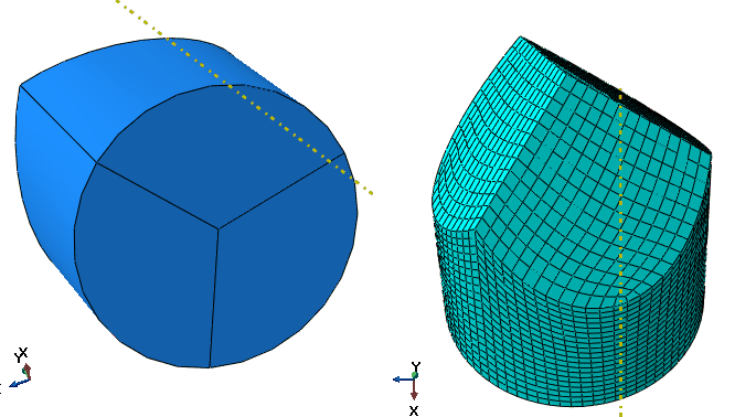
I need to mesh this part in C3D8 elements, but I'm getting a large number of element warnings (~13%) and my simulation terminates midpoint due to excessive element distortion. I have also tried C3D4 Tetrahedron elements but they give a stiffer result.

Please download the part here -
Somebody please help!
 
Replies continue below

Recommended for you

Here's a mesh that has fewer warnings about the element distortion that you might try. Firstly I removed the internal faces and then extruded the 3 lines at the top along a direction to partition the whole cell. The partitioned assembly can be meshed in hex or tet elements, but I can't see how you'd completely remove all warnings due to the overall geometry. If you use tet elements then use the higher order elements and not the C3D4 elements.

 
 http://files.engineering.com/getfile.aspx?folder=ace43ee3-d5c1-4f30-9ff7-e162c93d1256&file=pencilmesh.cae
Hi corus, Can't open your file on my version of Abaqus. Can you please post step by step screenshots with description?

PrtScr_capture_3_td1uop.jpg
 
In the part module remove all the internal faces you created to leave just a solid block with no internal partitions. In the Assembly module or the Mesh module create a datum line using the point on the flat circular bottom, that extends upwards in the direction of the axis of the part. Then extrude each line on the top part of the pencil shape in the direction of that datum line. You can do this twice then for the final line it'll ask which cell to partition. Select that cell and extrude the final line down in the direction of the datum line. The part will now have structured regions which you can mesh. For some reason the mesh shown is distorted slightly and you need to go in and redefine the partition on all curved lines around the pencil top. Here's a picture of the mesh and partitions used.

pencilmesh_a3sylu.png
 
Hi corus, I have tried your method and it works good to reduce % of warning, but is there a way to completely eliminate the warnings altogether??
 
Tetrahedral elements, C3D10, eliminate warnings altogether.

 
Hi corus,

Do you suggest me to use C3D10M instead of C3D8/C3D8R? What about accuracy and computational cost? Note that, I'm using ABAQUS/Explicit for a high strain rate event simulation.
 
Personally I wouldn't use C3D10M elements at all unless there was absolutely no option, say if the geometry was particularly complex and you can't easily partition it down. As you say, they're expensive to use and can give slightly inconsistent results when you view contours of the results. In general use quadrilateral brick elements but linear brick elements do work better in contact analyses. In that case use a higher mesh density for better accuracy.

In my experience I've tended to ignore warnings about element shape of brick elements unless they were in a region that was of particular interest but if they're particularly flat or a peculiar shape then I'd rectify the mesh, if possible. You can usually tell if you've got poor results by looking at result's contours to see if they appear to be mesh dependent.

 
"The quadratic tetrahedral elements in Abaqus/Standard (C3D10 or C3D10I) are suitable for general usage; but when used with contact, they should be used only with the “surface-to-surface” contact discretization. An alternative to these elements is the modified quadratic tetrahedral element (C3D10M) available in both analysis products. This element is robust for large-deformation problems and contact problems using either the traditional “node-to-surface” or the “surface-to-surface” contact discretization and exhibits minimal shear and volumetric locking. With either type of element, however, the analysis will take longer to run than an equivalent mesh of hexahedral elements. You should not use a mesh containing only linear tetrahedral elements (C3D4): the results will be inaccurate unless you use an extremely large number of elements."

[URL unfurl="true"]http://129.97.46.200:2080/v6.13/books/gsk/default.htm?startat=ch04s02.html[/url]
 
Hi corus,

In summary: there is no quadrilateral bricks in ABAQUS/Explicit, only linear bricks (C3D8R, C3D8 and C3D8I). The order of complexity and computational cost associated with these 3 elements are - C3D8R < C3D8 < C3D8I. C3D8R exhibits hourglassing but its computationally cheap, the rest 2 do not have hourglassing problem but much more computationally expensive since they are fully integrated.

Now, I'm using C3D8R and getting errors, see the image of a small part of my actual structure -
I'm getting 1 warning at the beginning of the analysis (White circle)-
18432 elements are distorted. Either the isoparametric angles are out of the suggested limits or the triangular or tetrahedral quality measure is bad. The elements have been identified in element set WarnElemDistorted.

And Analysis terminates as soon as the rigid plate touches the sample (Black circle). Note that its a drop impact test simulation -
The elements contained in element set ErrElemExcessDistortion-Step1 have distorted excessively.
There are a total of 2 excessively distorted elements
The elements contained in element set ErrElemExcessDistortion-Step1 have distorted excessively.
Abaqus/Explicit Analysis exited with an error - Please see the status file for possible error messages if the file exists.
 
The model shown in your latest picture looks nothing like the original model shown so it's difficult to advise further, particularly with the level of distortion as it's difficult to make anything out. The mesh does look particularly coarse though, which might be a problem. The advice in the manual is to use C3D8R elements to prevent hourglassing but I've found the opposite to be true and use C3D8 elements. If it crashes out straightaway then try using a different element to see if that works.

 
Hi corus, what is clear is that adaptive meshing (ALE) did not even start since distortion happens at the very first increment the rigid plate touches the sample. So I disabled ALE and will try "Distortion control in section control" for both Tetra and Hexa elements. The default value for Distortion control is 0.1, what is the maximum value can be used and what will be the implications?

The full model is bit confidential, I will email you personally if you don't mind. [smile]
 
Hi corus,

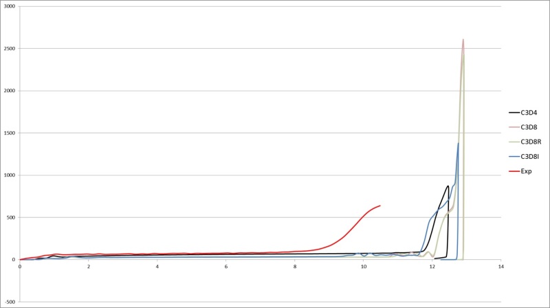
I have tested my model with (all) C3D4, C3D8, C3D8R and C3D8I elements. See the below picture of load-displacement curve of the structure. The Red line is the experimental load-displacement curve, you can see that C3D4 (Tetra) and C3D8I (Hexa, incompatible) elements give better result but it is not good enough.

Can you please suggest how can I improve the result, especially the meshing? One thing to note is, there are elements with warning at the joints for all cases (for all Tetra and Hexa elements).


Untitled_zrqzkc.jpg
 
You don't use C3D4 elements at all. If they gave good agreement then it's probably just a coincidence. In general a coarse mesh, and C3D4 elements, are too stiff to give good results. Your results in general don't seem to match the experimental results for any element when you consider the initial slope of the experimental results. Try refining the mesh until you get a reasonable agreement between two models. If the results then don't match the experimental results then you'd need to consider the assumptions you made in the model. For instance, can the rigid part be considered to be infinitely stiff compared to the rest of the model? Are your material properties accurate? Are the experimental results accurate? (I've seen so-called real measurements be incorrect)

 
Status
Not open for further replies.

Part and Inventory Search

Sponsor