Continue to Site

Eng-Tips is the largest engineering community on the Internet

Intelligent Work Forums for Engineering Professionals

  • Congratulations MintJulep on being selected by the Eng-Tips community for having the most helpful posts in the forums last week. Way to Go!

Pile to Cap Interface/Design

Status
Not open for further replies.

bookowski

Structural
Aug 29, 2010
971
This is related to a previous question I posted here (
Same pile assembly, steel casing w/grout and a large center bar - typically #18 75ksi. I've still yet to determine how the force is transfered into the casing but I'm setting that aside for now (seems like it relies on a local overstress that isn't accounted for).

The center bar carries a lot of load. If this is bar is developed by extension into the cap how does this affect the stm? Seems like this really complicates things - is the strut only a portion of the load, i.e. the load minus the component in the bar? Seems silly.

The only sort of logical solution I see is a bearing cap plate on the casing with the thread bar poking through. However this detail doesn't address load into the center bar unless it's got a nut on the underside, which implies that the plate is held high not tight to the casing.

The pile assembly gives huge capacities however they seem unworkable based on the stm strength at the node. As a cct node I'm capped at capacity .80 x phixf'c, so it seems like the only proper way is to come up with some kind of funky cap system that is large enough to make the node work and also transfer force to the various components.

I would like to say this doesn't work or do the funky detail but this pile with no special capping provisions is as common as white bread here and it's swimming upstream to say it doesn't work. These are high capacity piles though (600k to 3000k working load) so would like to know how (if) it works.
 
Replies continue below

Recommended for you

Forgetting my particular pile type - for any concrete pile that uses reinforcing and that reinforcing is developed into the cap (rather than some type of bearing plate/connection), how does that affect the stm? Sketch attached to clarify what I'm asking.
 
 http://files.engineering.com/getfile.aspx?folder=87ee9b7f-29d1-4b91-8bf1-965b9a424ec4&file=IMG_5207_-_Copy.JPG
I can think of three options:

1) Adjust the height of your nodes such that the rebar can compression develop between where it enters the nodes and where it exits the struts. This means that you need to lift your tie bars.

2) Use four struts instead of two with the lower going to the top of the pile and the upper going to the compression dowels. This will lead to a complex node at the top of the pile and the need for a second tie placed higher than the conventional one. It also means that you've got a tie crossing your struts. That's allowed but I generally try to avoid it.

3) You use two shear resisting mechanisms concurrently: your struts and punching shear for the portion of the compression dowel force that you're not able develop across your struts. Obviously, this method is pretty far off reservation and there are inherent difficulties in trying to properly account for the complexities associated with the two mechanisms working in tandem.

If it can be made to work reasonably, I'd prefer option #1. It's simple and the easiest to defend from a code standpoint. It may be quite inefficient with respect to the ties. I suspect that #3 is what is really taking place for common detailing out in the wild.

I like to debate structural engineering theory -- a lot. If I challenge you on something, know that I'm doing so because I respect your opinion enough to either change it or adopt it.
 
Thanks, KootK.

I'm struggling with this concept, there seems to be an incompatibility with high capacity piles and strut and tie - or it's revealing a big deficiency in how I typically see these detailed.

Unless I'm missing something you will always be limited by the nodal zone strength at the pile face. Lets say this is a 10" round pile of any type. This means you can get a max capacity at this node of Area x phi x 0.85 x Beta x f'c = PI()/4 x 10in^2 x 0.75 x 0.85 x 0.80 x 5ksi = 200 kips. 200 kips for a 10" pile is low, I have geotech designs for 600 kips (300T) 10" round. Seems like a high capacity pile requires other mechanisms to work, i.e. development into the pile which makes a simple stm not realistic.
 
bookowski said:
there seems to be an incompatibility with high capacity piles and strut and tie - or it's revealing a big deficiency in how I typically see these detailed.

I agree with the nature/scope of the problem. We've discussed both of the following in other threads but they apply here in spades:

1) With these connections, I often worry that there's a gap in who is taking responsibility. What I see in practice is geotechs providing suggested details for foundations and designers taking those recommendations as gospel without much additional checking. The truth is that the design of these kinds of connections is not within the scope/capability of most geotechnical engineers. Nor should it be.

2) Very similar conversations have been had here regarding column compression dowels. There's a cadre of structural engineers out there who seem to think that the only thing that matters for compression dowels is the compression development length. So what if the bars involved in the compression transfer are in different time zones. I see this as an upside down version of that to a degree.

I really hope that we get some feedback from some other folks on this. It's an interesting topic and potentially represents a pretty serious load path shortcoming.

I like to debate structural engineering theory -- a lot. If I challenge you on something, know that I'm doing so because I respect your opinion enough to either change it or adopt it.
 
One thing that seems to be lacking in the st provisions is an increase in the strength if there is some confinement. Not the same but if you look at the bearing provisions and the ability to go 2x the stress with just adjacent concrete as confinement it seems there should be something similar, some min % of steel that counts as confinement and allows higher capacity. The same 10" diameter using the bearing provisions would get you 433 kips, 2.15 times the capacity as the node check.
 
Just found the info below in some proposed revisions to aashto. Not familiar with aashto to know if these were picked up but makes sense and jives with my last post.

3.1.2 Limiting Stresses in Bearing Zones
 Current Specifications (5.6.3.5): The limiting stresses in the current specifications do not
account for the beneficial effects of confinement.
 Proposed Change: Introduce a factor to account for confinement for cases where “the
supporting surface is wider on all sides than the loaded area”. For simplicity and
consistency the “modification factor, m”, used in Article 5.7.5 – “Bearing” could be used
in Article 5.6.3.5 to modify the permissible bearing stresses where appropriate.
Effect of Proposed Change: This would reduce conservatism and maintain consistency
with the specifications in Section 5.7.5.


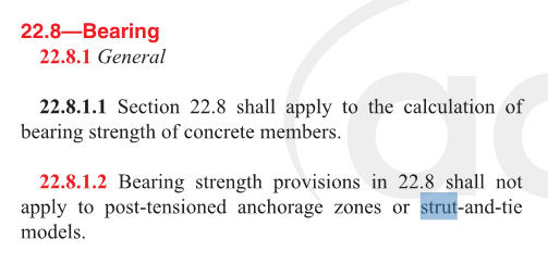
That is encouraging. It seems pretty clear that STM procedures have been constructed around 2D considerations and, no doubt, that is producing conservatism with regard to nodal bearing. It's a bit scary to contemplate going rogue on it, however, given the statement shown in 22.8.1.2 below.

Section 5.3.3 of this provides some unofficial support as well: Link

Cant_Column_muimw1.png


I like to debate structural engineering theory -- a lot. If I challenge you on something, know that I'm doing so because I respect your opinion enough to either change it or adopt it.
 
That's '14? I don't have a copy handy.

The problem is that I'm not trying to go rogue but explain away already rogue behavior to avoid reinventing the wheel and getting a lot of pushback.

 
Nice. That's "official" enough for me.

I like to debate structural engineering theory -- a lot. If I challenge you on something, know that I'm doing so because I respect your opinion enough to either change it or adopt it.
 
It seems to me that unless you use this there is no way to make any kind of reinforced pile work with st. You are limited to 0.75 x 0.85 x 0.8 x f'c = 50% f'c, so reinforcing in the pile would only make sense for uplift and/or bending. This negates almost all the pile designs I see locally (i.e. 90% of the piles under nyc).
 
I'll try to check out my copy of the CRSI doc on pile caps when I get home (annoying iPad only version). They're obviously getting pile caps to work somehow.

I like to debate structural engineering theory -- a lot. If I challenge you on something, know that I'm doing so because I respect your opinion enough to either change it or adopt it.
 
Found this presentation on their updated design guide (which I don't have) and I see a slide that says stm may be unconservative for some configurations/failure modes. It's just a slide so it doesn't elaborate.
ftp://ftp.dfi.org/SuperPile2015Presentations/02-Mays%20final.pdf
 
That unconservatism is actually something that I've been meaning to table with you as it affects the discussions that we've had in the past regarding walking columns without plan overlap. Apparently, there is a way to check a "direct shear-ish" failure mode between column and pile that would involve a diagonal shear looking crack at an angle steeper than 45 degrees. A bit of a game changer really. I've been slow to post because:

1) Damn thread's closed already and;
2) The iPad only business makes it difficult for me to clip snippets.

I like to debate structural engineering theory -- a lot. If I challenge you on something, know that I'm doing so because I respect your opinion enough to either change it or adopt it.
 
Yeah, as you know I've always been on board with direct shear being possible - just unlikely in most things we build. For non overlapping column walks I'd guess it always works easily unless you get really daring, and at that point you'd probably have horizontal thrusts that are not easily dealt with.

Found a paper on micropiles testing without bearing caps - Link
 
Status
Not open for further replies.

Part and Inventory Search

Sponsor