Continue to Site

Eng-Tips is the largest engineering community on the Internet

Intelligent Work Forums for Engineering Professionals

  • Congratulations MintJulep on being selected by the Eng-Tips community for having the most helpful posts in the forums last week. Way to Go!

To bad that touch constraint is not a real touch 1

Status
Not open for further replies.

Ehaviv

Computer
Jul 2, 2003
1,012
Hi

How its to bad that touch constraint is not a real touch
and is also an imaginary touch.

because if it was only a real touch we cood do limited rotation to some angle
as seen in these pictures.
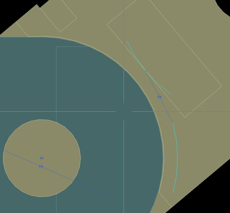
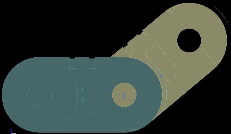
tip2_wbuxrw.jpg

tip1_q5arrm.jpg
 
Replies continue below

Recommended for you

With only pictures, I'm left to assume the beige component has a boss going into a hole on the dark green component and the boss is probably (again, this assumption due to images) the same height as the dark green component is thick in that general area - is this all true? So I can touch the 2 planar faces then align the boss with the hole axis. Once that is done, why do I need another touch? I need to define the angle between the 2 pieces, not touch 2 arcs together - or once again are we missing information the images do not provide?

Post parts if possible, please - makes it easier to see what you've actually done when you don't take us through each step.

Tim Flater
NX Designer
NX 9.0.2.5 Win7 Enterprise x64 SP1
Intel Core i7 2.5GHz 16GB RAM
4GB NVIDIA Quadro K3100M
 
Thank you Cowski

That's good and far because my company
recently upgraded to nx8.5 and from history
I'll should wait two years for that.
 
A work around is to use a spline for the cam curve, then the solver will prevent the point follower from moving beyond the desired range.

okYsi.png


But NX8.5? Really? Support was ended last year for that version or do you not pay maintenance?


Thank you Petulf
this is good trick
I'll try it
 
Thank you Petulf

Your work around work very good.

But I need to move the handle to the rotation axis before moving the free link
if the handle is not on the rotation axis the free link refuse to move.
Do you experienced this.
 
 http://files.engineering.com/getfile.aspx?folder=e453e04f-9b06-4d77-84fc-58c6c0b8b07d&file=chain_test_3.zip
Working as intended, the assembly solver prevents motions in constrained directions. If you need the chain to follow a certain path i would constrain it to a spline with the minimum radius derived from the allowable degrees rotation of the chain links, this would also allow you to skip the previous mentioned "workaround".

2x9HW.png


I played around with this quite briefly.
- smart move there to use the Join Curves to convert the Arc to a spline , i would not have thought of that option. :)
( otherwise i am kind of "allergic" to the Join Curves, I see it used ( ex Catia people ?) as a selection method, which isn't that good since it will create an approximation spline on top of the original objects rather than a "selection group".)
It seems that it doesn't need the sharp corners shown by Petulf. If I edit the Join Curves and remove the lines , it works the same.

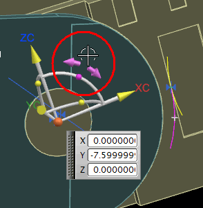
Anyway, a little trick to avoid the handles of the Move Component.
( - If I pick the "ball" on the arc I can rotate freely, i do not need to move the handle.)
rotate_ier76f.png


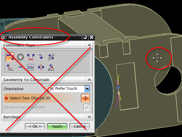
Start the Assembly constraints dialog instead of the Move Component. Then place the cursor anywhere on the component to move, press and drag. It will move within its possible limits.
move_o8pp6a.png


Regards,
Tomas
 
Toost, cool did not think to check if one needed a discontinuity or not, using only the arc makes the entire thing cleaner.

As for join curves I mostly use it for these sort of occasions IE when constraining something(sketch/asm) to a curve and there is no selection rule available.

 
Sorry for hijacking the thread.

I have seen quite a few videos from "NX specialists" where they use Join Curves before creating surfaces.
- probably because some other cad system "prefers" to have a single object per section in the surface definition.
I am afraid that one then risks two times approximation, first the curves are approximated into a single spline. ( with G0, G1 continuity etc)
then that spline is approximated again when used in the surface.
If NX is smart enough it reads the original curves , but i don't know how to check that.

Regards,
Tomas
 

Thank you petulf
Thank you Tomas

On the new helpful info.
 

I removed the corners lines (arc spline only)
and start the Assembly constraints dialog instead of the Move Component
and the drag works smoothly.

Thank you Tomas for these tips.
 
Status
Not open for further replies.

Part and Inventory Search

Sponsor