Continue to Site

Eng-Tips is the largest engineering community on the Internet

Intelligent Work Forums for Engineering Professionals

  • Congratulations KootK on being selected by the Eng-Tips community for having the most helpful posts in the forums last week. Way to Go!

Local Flange Bending - Equipment Skid

Status
Not open for further replies.

pperlich

Mechanical
Jun 17, 2014
114
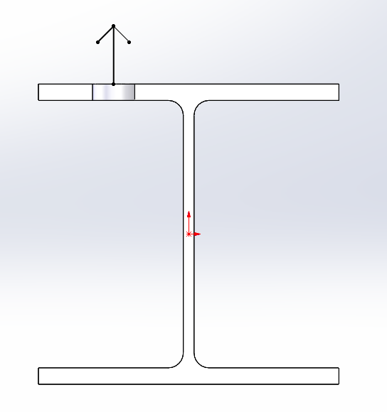
I have an equipment skid made with a W8 x 31 beam frame. How would I check if the flange is adequate for a force on the flange applied by a bolt as shown? I was looking at AISC J10.1, but I'm not sure that section is applicable to a single bolt. It seems to be geared more towards plates welded across the flanges to limit the stress concentration at the web.
blob_fyaqjw.png


Thanks in advance for the help.
 
Replies continue below

Recommended for you

You could assume a 45 degree load spread back to the fillet and check plastic bending strength there. Or get fancier and work out a yield line analysis. Depending on your setup, you may have bending in the web as well.

I like to debate structural engineering theory -- a lot. If I challenge you on something, know that I'm doing so because I respect your opinion enough to either change it or adopt it.
 
If you don't find anything specific to this situation-
Treat the flange as a triangular wedge spreading out at 45 degrees each side from the bolt hole and checking bending at the web.
For a one-off design, it may be cheaper to weld a stiffener in than to show it isn't needed.
Or it may be worthwhile to revise to a design that you can analyze easier.
If you're doing a lot of identical units, then finite element or physical tests.
 
The AISC design guide on bolted end plate moment connections has a flange bending limit state. This is caused by one bolt in each flange of the column. But, you could use the same equation with halt the capacity.
 
A single bolt on one side is more critical than half of a double bolt because moment goes into the web and the web is likely thinner than the flange.

BA
 
Pperlich:
The advice you’ve been given above is right on the money for the single bolt force you have shown, but that may not really be the critical (or only) force at that location. Generally, the equip. sits on the skid and those bolts mostly hold the various parts together and on the skid. There will be equip. foot/pad bearing stresses on the beam webs. There will be beam bending and shear stresses as the equip. loads the skid beams btwn. their support points, etc. You have to look at the whole system, and that includes deflections, the relative stiffness of the various parts, etc. What load or lifting conditions cause the bolt load you show?
 
A similar situation is discussed in 2001 (3rd Quarter) AISC Engineering Journal paper "The Performance and Design Checking of Chord-Angle Legs in Joist Girders" by Theodore Galambos. I suspect the approach discussed in this paper can be adapted to your situation. The paper is available at and is a free download for AISC members.
 
Status
Not open for further replies.

Part and Inventory Search

Sponsor