Continue to Site

Eng-Tips is the largest engineering community on the Internet

Intelligent Work Forums for Engineering Professionals

  • Congratulations waross on being selected by the Eng-Tips community for having the most helpful posts in the forums last week. Way to Go!

Surface Preparation for Long-Slotted Shear Connections Subjected to Eccentricity

Status
Not open for further replies.

MGaMart

Structural
Aug 23, 2016
50
For slip critical connection, I always call off a "NO PAINT" requirement at the bolt line to ensure the appropriate surface class is maintained. When dealing with connections attaching to existing steel, I always provided horizontal long slots for erection allowance. If I were to have a hz long slotted shear connection where the bolts are subject to eccentricity effects, does the connection get forced into a slip critical condition (i.e. requiring the "NO PAINT" requirement)? I guess the question becomes is the connection still defined as bearing, as a moment due to eccentricity imposes a force couple on the bolts. The vector sum of the force is then not perpendicular to the longitudinal axis of the long slot. How's my reasoning on this? To be on the safe side, a "NO PAINT" labelling should be included, but is it truly required? (NOTE that when either slip critical or long slotted connections are used, the bolts are always pretensioned). Feel free to point me to any literature on the subject.
 
Replies continue below

Recommended for you

I'm not clear on why there'd be a moment on this connection. Are you attempting an extended shear plate connection design?

I like to debate structural engineering theory -- a lot. If I challenge you on something, know that I'm doing so because I respect your opinion enough to either change it or adopt it.
 
 m
Precisely. I failed to mention the "extended" portion. Typically in my designs when using long slots, I always inherently view them as extended (eccentricity effects included) given the increase in minimum edge distance and the worst case of the bolt @ the extreme side of the long slot. This transitions into the question of the threshold when eccentricity should be accounted for and when it can be ignored (but I'll leave that for a future thread discussion).

My original question pertains to applying the Instantaneous Centre of Rotation Method for eccentric bolt groups in conjunction with long slots.
 
This doesn't sound like an extended shear plate connection in the AISC manual sense of the word. Rather, it just sounds like a shear tab with potentially more bolt line eccentricity than usual. As such, I don't feel that you need to resist a moment on the bolt group nor worry about slip critical surface prep. That said, I do agree that a slotted bolt group resisting a moment would need to be slip critical and the faying surface would need to be prepped appropriately.

I like to debate structural engineering theory -- a lot. If I challenge you on something, know that I'm doing so because I respect your opinion enough to either change it or adopt it.
 
This is what I mean from the development of moment at the bolt group (image taken from 2002 AISC Report: Design of Extended Shear Tabs)

Bolt_Line_Eccentricity_fm4kjd.png


Its my understanding that failure to resist moment @ the bolt line would then introduce moments into the supporting member (which is not an encouraged practice). The Instantaneous Centre of Rotation method (ICR) essentially comes down to the fact that the bolts are resisting a shear load in addition to a moment derived from the shear load at a distance 'e' from the supporting member.

I've found a clause in the 3rd ed of the AISC Manual stating that slip critical joints are not required if the load is "approximately" normal to the direction of the slot (within 80 to 100 degrees). As this version is the only one accessible to me, I'm not sure if it has been updated in terms of verbiage. (Disclaimer, I'm Canadian and only refer to the AISC periodically; the CISC seems more restrictive by not including the "approximate" wording in their clause).

Combining the AISC wording of "approximately" normal with ICR would suggest that slip critical conditions in some scenarios could be avoided. Of course, its safer to design for slip critical, but this does come at the cost of a less economical design (i.e. additional labour time to mask off NO PAINT regions on members and connection plates).
 
OP said:
moments into the supporting member (which is not an encouraged practice)

I don't think it's a big deal so long as you account for it. Every moment frame ever dumps moment into the columns. Additionally, even with an extended shear tab, you're still putting moment into the support. It's just capped at the moment at which the shear plate would plastify in flexure.

I see designating the bolt group as moment resisting as being a choice. Pick a path and deal with the associated issues. It would help here to know the details of what you're dealing with. The geometry of your connection and such. In these situations, it is common to slot the shear tab holes but still not go to an extended shear plate connection. It's more eccentricity but not usually that much more.

I would avoid the slip critical connections if at all possible. Proper inspection of those adds real cost. If your geometry is such that you really need to do an extended shear tab, you could do it with two columns of bolts so that you can develop a moment capacity without requiring bolt forces parallel to the slots. I've never done that but it seems rational.


I like to debate structural engineering theory -- a lot. If I challenge you on something, know that I'm doing so because I respect your opinion enough to either change it or adopt it.
 
Keep in mind, that the image I showed is just generic to depict the design moment at the bolt line. I agree that moment, however small, can and will transfer into the supporting member. Attaching to the flange of a column is the best case scenario, as moment will be resisted in the column in the strong axis..... but if we have scenarios where a shear tab transfers into the web of a beam or column, your connection becomes far more robust with the need to include stiffeners (for the column) and full depth plate connections (for the beam); not to mention creating torsion now in the beam (which may or may not be ignored).

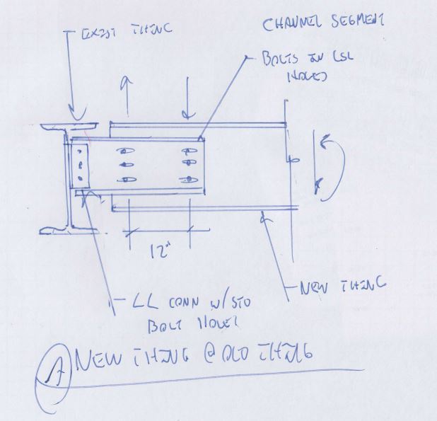
My question stemmed from doing work for retrofit jobs. Connecting into existing steel almost immediately requires the use of long slots (unless extensive surveying is conducted and even then does not guarantee successful bolted connections). When connecting a new beam to an existing beam that runs perpendicular, we often like to stop the new beam short of the toes of the existing beam flange for ease of erection (i.e. new beam is not coped to fit inside existing beam). Working for a steel fabricator (and especially for retrofit jobs) we are not always privy to all loads in the structure, so intentionally developing moments and torsion by not accounting for moment resistance @ the bolt line is neither conservative nor good practice.

As a side note, I loathe slip critical connections. They're an overly used and often unnecessary part of connection design (unless you're building some kind of quantum microscope facility where structure movement can't be tolerated) [tongue]
 
This is a method that I've used in retrofits to easy installation and inspection. Got the idea from some cladding support beams the Seattle public library.

Capture_mkwmjk.jpg


I like to debate structural engineering theory -- a lot. If I challenge you on something, know that I'm doing so because I respect your opinion enough to either change it or adopt it.
 
Thanks for all your input on this subject KootK. The connection you showed would definitely do the trick. It's not one the company I work for uses as a standard, but good to keep it in the back of my head for a rainy day. I have seen this type of connection in the field once, but they used the channel merely as an extension piece because the beam was cut too short (field welded instead of bolted though).
 
Yes, the connection you describe, a shear tab with long-slotted holes, should have the bolts in a slip critical condition. There is moment on the bolt group, and the normal resistance of bolts bearing against the plate won't be achieved due to the long slots.

This is not documented anywhere in the AISC literature that I know of, but it is my understanding of the requirements of the shear tab procedure. I did ask Dr. Pat Fortney in person this question at the steel conference a few years back, and he confirmed that this is how to consider long-slotted holes in shear tabs.
 
The literature I found from AISC Manual (3rd edition) is found on p16.4-26 (please inform me if the literature has been updated in the most current edition):

"Slip-Critical Joints
Slip critical joints are only required in the following applications involving shear or combined shear and tension:
...
(3)Joints that utilize slotted holes, except those with applied load approximately normal (within 80 to 100 degrees) to the direction of the long dimension of the slot"

This gives rise to interpretation, but it can be argued that if the ratio of shear normal to the slot (i.e. gravity loads) to the shear parallel to the slot (i.e. moment at boltline resolved into a force couple) is high, enough so the resultant vector force applied to each bolt is within the 80-100 degrees specified, then the use of slip critical conditioning is not mandated.

Again, the main question I was seeking to answer was not if long slotted holes in eccentrically loaded shear connections "should" be treated as slip critical, but whether it "shall" (to use the code terminology) be treated as slip critical
 
I've had this issue come up before, and it always bugs me that we seem to be intent on forcing some moment transfer out of these plates now. Where is the mechanism for end rotation? Can we assume that the beam is a simple span beam with just a vertical shear reaction at the end?

If for whatever reason the holes didn't align and the fabricator wanted to weld the shear tab to the beam web, we would all argue that there is no rotational ductility in the connection. Now with SC bolts we're OK with that?
 
It's a good question sbisteel. I suppose end rotation mechanisms form through elastic deformation in the shear plate. I think the intent is to try and mitigate the development of moment in the supporting member as much as can be afforded. In a simply supported case, zero moment exists at each end of the member. If the "end" of the member is the bolt line of the beam (where rotation mechanisms intuitively form), a moment forms from the jump from bolt line to the face of the supporting member. If however we take the "end" of the member as the far edge of the shear plate (beyond the end of the beam), the bolt line must resist some moment in order for the beam/shear plate to be treated as a single continuous member. In reality, welding the shear plate to the supporting member will create stiffness that attracts moment (to somewhat paraphrase what KootK mentioned in an earlier post). The difference lies in the amount of moment being transferred to the supporting member. If the bolt line is designed to resist moment, the location of zero moment in our simply supported case lies somewhere between the bolt line and the face of the supporting member, with a moment value less than it would be had the bolt line been design to resist no moment. At this point, I feel it accepted practice to ignore the moment transferring into the supporting member (if it is small) and only design for the shear load (maintaining the simply supported model). The end rotation mechanism isn't clearly defined I'll admit, but I guess that is the divide between how we design connections and how the beam actually behaves. Please feel free to correct/critique my understanding of this subject if something doesn't fit with current industry practice.
 
End rotation occurs from deflection of the beam. There is shear flow in opposite directions resulting in horizontal shear parallel to the slots.
 
Isn't end rotation predicated on boundary conditions? Obviously the loading causes the beam to deflect, but the rotation @ the end depends on the degree of fixity and whether the connection detail can sustain bending moment or if it acts as a hinge (pin connections being the prime example). The bolt line is intuitively the first location to think of where end rotation can occur (due to the ability for the bolts to move in the hole). Slip critical connections restrict this movement. My understanding is that the location of the point of contraflexure (zero moment) migrates away from the bolt line because of its ability to resist moment. For the case of a shear plate, the weld to the supporting member also attracts some moment into the supporting member, and so the location of zero moment lies somewhere between the weld line and the bolt line. As I mentioned earlier, in practice we omit the moment into the supporting member (as it is likely quite small) and simply design for the shear load.
 
Status
Not open for further replies.

Part and Inventory Search

Sponsor