Continue to Site

Eng-Tips is the largest engineering community on the Internet

Intelligent Work Forums for Engineering Professionals

  • Congratulations SDETERS on being selected by the Eng-Tips community for having the most helpful posts in the forums last week. Way to Go!

Lateral Torsional Buckling of Thin Beam

asalisbury

Mechanical
Mar 6, 2024
13
I am working on determining if I have any lateral torsional buckling in this beam. I can't really find any equations for this specific scenario so any help or pointers would be appreciated. It's a very thin and long metal beam that is getting loaded on each end with 5,000lbs. It is pressing into a simple support that covers most of the beams span.

1741797557540.png
 
Replies continue below

Recommended for you

Don't think I'd really call that beam as it has essentially zero bending stresses in it. So no LTB, but plate buckling is likely. And then just general stability if there's nothing bracing the top edge.
 
Is this a beam on elastic foundation? Will you provide more info. for ( 25 in simple support, restrains at both ends , ..) and review your figures. If the thk. 0.05 in, the plate will buckle with very small loading before LTB.
 
I don't see how 20mil sheet could handle 50 lbs, let alone 5000 lbs? That's just a hair thicker than a 25 gauge drywall stud.
 
Yea running through this with the typical web bearing at beam end equation (not that it would necessarily translate perfectly without a flange) I get a capacity of 225lbs roughly. There is zero chance this is holding 5000lbs.

A typical paperclip is thicker than the beam you are proposing.
 
You probably need to worry about end bearings in additional to bending
 
My force was not right, it is getting distributed over many of these. Each end is getting 19.5lbs applied. We have a set of combs that hold each end in place and resists torsion. This does seem to fall under plate buckling and not beam buckling. 1741807477754.png
 
I would assume that the load is reacted near both ends, rather than distributed. It would be a "nice" shear lag problem to distribute.

I would assume a 30t width effective in compression (this is a standard assumption in my field) so effective width 0.6".you could use the width of your guides

I would assume a 2" long column, you could finesse with the distance between the guides.

This is steel, yes?

So Peuler = pi^2*EI/L^2 = 10*30E6*(0.02*0.6^3/12)/2^2 = 10*30E6*3.6E-4/4 = 27000 lbs ! but this is a stress of 2E6 psi !!

Your load produces a stress of <2ksi ... which should be good by inspection.
 
well he is an "EIT" but he should've gotten further into the problem on his own.
 
We started with a 5000# load at each end. Now, because there are "many of these", the load has reduced to 19.5#, so "many" turns out to be about 260. How far apart are the plates? What type of member can apply a load of 5000# uniformly over a span of 260s where 's' is the spacing of plates?

Does the simple support deflect over its 25" span, or is it deemed to be rigid? If rigid, I agree with rb1957 that the load is carried over a very short length at each end of the support, so LTB over a span of 25" is likely not a problem.

A plan and typical sections of the assembly might help our understanding of the problem.
 
So Peuler = pi^2*EI/L^2 = 10*30E6*(0.02*0.6^3/12)/2^2 = 10*30E6*3.6E-4/4 = 27000 lbs ! but this is a stress of 2E6 psi !!
I think you got your b and t backwards for moment of inertia since it will be buckling in the weak axis direction, no? b = 0.6", t = 0.02".

Peuler = 30 lbs, at 2.5ksi.

Either way, I don't think we have an accurate picture of the problem statement. Is this "assembly" like some sort of heat exchanger or something? Very thin fins supported at the ends by some sort of frame? Like the fins on a radiator. And the force is from the frame being pressed around the fins, or vice-versa?
 
So I did some more work on this and got a better understanding of the problem, but am still a bit shaky on this stuff.

Things I figured out:
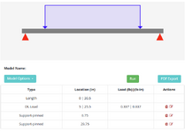
  1. We can use the scenario for an equally loaded partially distributed beam, where the simple support is acting as a uniform distributed load, and the pin supports are essentially the applied load.
  2. The loading is 2200lbs across the 256 beams, so 8.59 lbs per beam. (for confidentiality purposes I cannot disclose what kind of system this is)
A few questions:
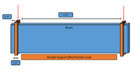
  1. I am not entirely sure what my braced length is here, we have combs (in orange) that apply force to the beam and provide resistance to rotation. Is the braced length the distance between the two combs?
  2. I calculated that the Nominal flexural strength is 118 in-lb and the plastic moment capacity is 634 in-lbs, so that means that LTB is the governing failure mode and reducing the beams total ability to resist loading? (AISC F11)
  3. I then calculated the design flexural strength as 106.92 in-lbs and the allowable flexural strength as 71 in-lb where the maximum moment is 32 in-lbs, so the beam can safely handle the applied load?
1742481478686.png
1742480931492.png
 
the scenario for an equally loaded partially distributed beam
it would really help to know what this thing is in reality, and where the real loads are coming from.
where exactly is the load applied? to the orange bars? to the blue beam?
this appears to be a plate buckling problem, with 3 sides supported. why not make a simple FEM of one plate and run a buckling analysis?
 
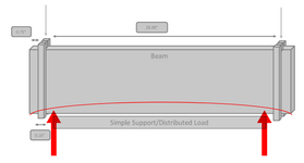
Still seems to me like these fin things are simply going to get squashed right at the edges of your support. The "beam" (fin thing) will deflect upward ever so slightly and at that point all of your reaction forces will be concentrated at the edges. I probably wouldn't approach this as a continuously supported beam or beam on elastic foundation type problem. Crippling and web buckling would seem to dominate over beam action / flexural effects.

Furthermore, I'm not sure AISC would really be the appropriate code to use. AISI would be more suited to elements like this. Or some other sort of mechanical engineering codes which I know nothing about.

1742486702942.png
 
So I did some more work on this and got a better understanding of the problem, but am still a bit shaky on this stuff.

Things I figured out:
  1. We can use the scenario for an equally loaded partially distributed beam, where the simple support is acting as a uniform distributed load, and the pin supports are essentially the applied load.
  2. The loading is 2200lbs across the 256 beams, so 8.59 lbs per beam. (for confidentiality purposes I cannot disclose what kind of system this is)
A few questions:
  1. I am not entirely sure what my braced length is here, we have combs (in orange) that apply force to the beam and provide resistance to rotation. Is the braced length the distance between the two combs?
  2. I calculated that the Nominal flexural strength is 118 in-lb and the plastic moment capacity is 634 in-lbs, so that means that LTB is the governing failure mode and reducing the beams total ability to resist loading? (AISC F11)
  3. I then calculated the design flexural strength as 106.92 in-lbs and the allowable flexural strength as 71 in-lb where the maximum moment is 32 in-lbs, so the beam can safely handle the applied load?
View attachment 6831
View attachment 6827
What is the width and depth of a typical beam?
  1. What is the gap between beams?
  2. Is the length of each comb 256(width+gap)?
  3. Each tooth of each comb is 0.16" x gap?
  4. The load on the simple support can't be uniform if the beams deflect upward and the support remains level.
  5. The loads on the orange combs can only be equal if applied by a rigid body such as a vertical plate or girder spanning all 256 beams.
  6. How is it possible to deliver an equal load to each beam?
With regard to your questions:
  1. Your unbraced length (not braced length) is the distance between combs, assuming that the teeth of the combs prevent beam rotation.
  2. I can't confirm your calculation as I don't know the dimensions of the beam, but the difference between flexural strength and plastic capacity seems high at first glance.
  3. Allowable strength is about 66% of flexural strength, which seems reasonable. Maximum moment should be much less than 32"# if the beam reactions are near the ends of the simple support rather than uniform across it.
 
Last edited:

Part and Inventory Search

Sponsor