Continue to Site

Eng-Tips is the largest engineering community on the Internet

Intelligent Work Forums for Engineering Professionals

  • Congratulations SDETERS on being selected by the Eng-Tips community for having the most helpful posts in the forums last week. Way to Go!

Why is the maximum sagging moment being used in the LTB checks when I have restrained the top flange? 1

BA123

Structural
Mar 11, 2025
4
Hi,

I'm posing this question, as it seems that Tekla Structural Designer is using the maximum moment when checking the LTB of the bottom flange, for a fixed ended beam, this max moment in the section can be a sagging moment (i.e. bottom flange in tension), if it has the greater magnitude.
I would have thought the logical moment to use for checking LTB of the bottom flange is the hogging moment, where the bottom flange is in compression. There is a tekla support article (which can be found by googling my thread title), that references "Annex G for BS 5950 and Section 6.3.2.4 of EN 1993", but I'd like to know why the max moment is used regardless of which flange is in tension/compression and not just "this is the code".

Can anyone explain the reasoning behind this?

Thank you
 
Replies continue below

Recommended for you

The top flange is fully restrained. LTB for the top flange is not checked due to this:
View attachment 6494

The bottom flange is fully unrestrained (hence LTB length is set to full length), however only experiences compression for only a short segment length where there is hogging moment. The use of maximum sagging moment is confusing to me as it can be very large vs small hogging.

I only demonstrated the effect of having very small hogging moment, by reducing fixity, to highlight the problem (of course if in reality I had only 1kNm hogging I would just switch the beam to simply supported and avoid the whole issue). The actual hogging moment, as shown in my first screenshot is 153kNm (still much smaller than the max sagging of 350kNm). In my mind LTB is caused by compression in the flange which for the bottom flange only occurs with hogging, so taking the sagging moment seems incorrect.
This is kinds of weird.
Nevertheless, to my best knowledge, fundamentally if you have a restrained on the compressive part of the member, in this case, 350.9kNm (sagging) will be on top part of beam, the LTB length should be reduced to corresponding length. If you pretty sure that it will not buckle as you restrained it, probably you may need to manually adjust the length as it seem Tekla do not capture it, therefore it shows LTB length is the full length.

I believe we have already establish that bottom is tension, should not experience LTB. So you may need to check why Tekla still using full span, is it limitation of software, or is there any other feature/option we haven't look into. I haven't use Tekla before but fundamentally is the same.
 
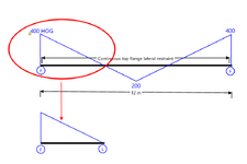
@Tomfh Like in image? I ran one case in LTbeam. Critical moment was >50% higher for 4m FL beam than 12m beam with continuous top restraint. If not what you mean how would you use AS4100 for this beam?Continuous-lateral.png
 
Yes I would do it like that. A 4m beam with triangular bending moment, and design moment of 400kNm

I’m not really sure what our disagreement is here?
 
I dont think AS4100 covers this case except using buckling analysis.
Personallt I think AS4100 assumed simply supported so unconservative in cases that qualify as full restraint but others have design rules.

I might be flogging the horse that Tomfh has already flogged... But this is simply not correct.

Tomfh has explained why. If anything AS4100 is possibly slightly conservative in cases where there is hogging and the bottom flange is well restrained. Though given that segments with hogging moments are generally short this likely doesn't crop up much.
 
Yes I remember now. AS4100 civers but unconservative. L restraints work how it says for single curvature but also used for reverse curvature. For case in image with IPE600 section it's almost 50% overestimate of critical buckling moment.
 
Yes I remember now. AS4100 civers but unconservative. L restraints work how it says for single curvature but also used for reverse curvature. For case in image with IPE600 section it's almost 50% overestimate of critical buckling moment.
You are going to have to elaborate on that. Why are you saying that AS4100 is unconservative and overestimates the critical buckling moment by 50%?

By a margin like that you have to wonder why portal frame constructions aren't falling over all over the place when using AS codes.
 
@human909 Could be lots of reasons. Usual things like unrealistic design loads, load factors, safety factors. Governed by deflection or other part of rafter length. Could be because that Portal Frame Design book says ignore purlin restraint in reverse curvature and take full length between fly braces. Sounds like they understand issue. Could be they do fall down when actually get gravity load like when six fell down same day at Huntingwood when it hailed.
 
You still have explained the issue.

If purlin restraint where the moment is reversed is straight out of AS4100.

You have made a bold claim. It would be nice if you actually explained with an example why.
 
Thought of another reason portal frames not having the problem. Fly brace at end of haunch gives F restraint.

Here's what Design of Portal Frame Buildings book says. Bradford coauthor and also coauthor of AS4100 section 5 commentary. People designing how this book says will avoid problem.

Section 4.3.2.3 – Bottom Flange in Compression – With Fly Bracing under Uplift – “The moment modification factor alpha_m for segments between fly braces will usually be greater than 1.0. For segments which have a reversal of moment, part of the segment will have its compression flange restrained by purlins but this benefit should be ignored.”

Section 4.3.2.3 – Bottom Flange in Compression – With Fly Bracing under downward Load – “The effect of the bottom flange near the columns being in compression due to gravity loads or other loading should be considered even though most of the bottom flange of the rafter is in tension. A fly brace is recommended near each knee and near the ridge. With fly braces at least at the knees and the ridge, the effective length will be 0.85 times the spacing between fly braces.”

Section 4.10.4.2 – Design example – “Within a rafter segment which has reversal of moment, it is not theoreically feasible at this stage to take advantage of the fact that the compression flange is restrained by purlins over only part of the segment. Therefore, the restraint from all purlins within the segment is conservatively ignored. Consequently, the fact that the maximum bending moment end has compression in the laterally restrained top flange is irrelevant.”

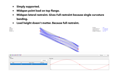
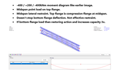
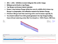
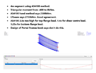
Images shows issues. First one, simply supported, shows how lateral restraints are supposed to work. When one flange entirely in tension, lateral restraints enough to keep the whole section vertical just like F restraints. Second image shows bottom flange kicking out when have compression in it for part length even though have lateral restraint at top flange. Not what AS4100 assumes when you look at the Le factors, L restraint is equivalent to F restraint. Third one is same for continuous top flange restraint, also not effective for bottom flange. Fourth one is the AS4100 case (if ignore what Portal Frame book says). I now have 2.5x overestimate when move load to top flange. Seems like a lot but using moment diagram to magnify issue. Real moment probably not so severe. Not too much surprise when using 4m instead of 12m as effective length. Yura method is similar to buckling analysis but doesn't quite cover this case so take as approximate only.
 

Attachments

  • 1-simplysupported.png
    1-simplysupported.png
    58.8 KB · Views: 30
  • 2-reversecurvature.png
    2-reversecurvature.png
    63.9 KB · Views: 29
  • 3-continuous.png
    3-continuous.png
    67.7 KB · Views: 26
  • 4-AS4100segment.png
    4-AS4100segment.png
    62.7 KB · Views: 32
What do you get with -

1. No lateral restraints
2. Bottom flange lateral restraints
 
Thanks smoulder. It still isn't a 100% clear to me but I think I need to do my own digging. Is this a 12m IPE600 beam?

Thought of another reason portal frames not having the problem. Fly brace at end of haunch gives F restraint.

I can't say I'd ever feel comfortable designing a typical portal frame without fly braces.

A slight aside I am in the midst of designing a row of portal frames with 1000kN bearing on the top flanges of each 610UB which have no web framing members. A total of 9000kN in a 5m x 33m x 12m heigh portal structure!

I have yet to delve into the requirements of bottom flange restraints but my gut tells me that I shouldn't view the situation in a trivial fashion.

Additionally the load can be eccentric to the beam and so potentially introduce torsion. It will be an interesting issue. I believe it is all workable, just need to look deeper when I get the time. At the moment it is just a preliminary design.
 
@human909 Yes, 12m IPE600. But now switching to British UB 610x229x125 so can compare with similar British LTB software. You doing bulk solids work to get 900 tonnes?

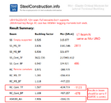
@Tomfh See image below. Used SCI Mcr online analysis tool because easier to do multiple cases. But then checked with LTBeamN which is French and used for images in last post. Some concerning differences but still need to be convinced AS4100 isn't unconservative for lateral restraints in reverse curvature like Portal Frame Design says.
 

Attachments

  • TomfhResults.png
    TomfhResults.png
    177 KB · Views: 26
You doing bulk solids work to get 900 tonnes?
Absolutely! And plenty of it! And one thing about the bulk solids world is that we regularly close or exceed our unfactored live loads! 😨 Many other structure likely don't.


Back on topic...

I'm confused by your RC cases why is 200kN point load for a 12m beam is producing 400kNm hogging at the supports?

Either way the answers I get for a 12m 610UB125 fixed ends are:

From SPACE GASS, A4100
ϕMbx = 927.36 kNm Continuous top restraints
ϕMbx = 648.65 kNm T&B RESTRAINTS AT 4m & 8m

From Clear Calcs EU
Mb,Rd= 752kNm RESTRAINTS at 4m & 8m

None of these have been hand checked by me today. I have certainly extensively reviewed SpaceGass against hand calcs as I'm sure thousands of Australian engineers. I don't know where you are getting your MCr of 3162.31kNm from unless you have a 10m beam, using ϕϕMo.

For the record I'd more than happily be shown that AS4100's approach to beam buckling is problematic. I hardly see it as the golden solution. But to say it is extremely unconservative is certainly a strong statement that needs to be supported. KootK, I and others debated LTB extensively years back. Have a read if you dare. I am certainly a much more experience engineer now than I was over half a decade ago! :LOL:
 
Last edited:
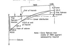
Within a rafter segment which has reversal of moment, it is not theoreically feasible at this stage to take advantage of the fact that the compression flange is restrained by purlins over only part of the segment. Therefore, the restraint from all purlins within the segment is conservatively ignored. Consequently, the fact that the maximum bending moment end has compression in the laterally restrained top flange is irrelevant

That is from older edition of the book. See how they wrote it in terms of "not theoretically feasible at this stage", as in they were working on it. See the figure below, showing L=7800 flybrace-to-flybrace segment length, in accordance with that philosophy.:

3rd EDITION.jpg

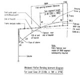
Edition 4 version has changed its mind and says instead: "As this length of rafter has reversal of moment, purlins which are attached to compression flange are deemed by AS4100 to be full restraints. Hence the segment length will be 5600 from the first purlin past point of contraflexure to the fly brace". See here, the revised Figure, showing shorter segment length:

4thedition.jpg

I don't have edition 5, so not sure what its current position is, lol.

Maybe it's not always right to treat L-restraints on the compression flange as full restraints in every scenario. To be honest, it's always felt a bit sketchy to me—especially since the compression flange doesn’t necessarily move when buckling. But in any case, AS 4100 and this Portal Frame book both say it’s fine, and they’ve actually thought it through. The book has gone from "not theoretically justified at this stage" to allowing it, so it’s clearly not just an oversight.
 
Last edited:
I don't have edition 5, so not sure what its current position is, lol.
No change in Edition 5. I have a hard copy in front of me now.

Though I would say that that at best the Design of Portal Frame Buildings should be used as a help to interpret AS4100. Ultimately AS4100 is the code and it is either suitably conservative as written and interpreted or it isn't. The portal frame building design guide is somewhat a distracts. Plenty of portal frames are designed and built by following AS4100 rather than referencing this guide.
 
Ultimately AS4100 is the code and it is either suitably conservative as written and interpreted or it isn't.

Yeah, agreed—that’s the question. It's sure is murky though. The code says to treat L’s like F’s once a flange goes into compression, and the Portal Frame guide appears to follows suit in the later edition. But L = F feels pretty loose—you can find examples where a beam buckles right through the L. Does that actually matter? Hard to say. Maybe the code has it covered, or maybe safety factors and incidental restraints have been masking the issue all along.
 
Yeah, agreed—that’s the question. It's sure is murky though.
I agree that it is murky, but it all seems to work in a manner that is more simple to apply than other codes (as I understand it). I believe that was Kootk's conclusion after the long winded thread linked earlier. Other codes are also murky for me, but that is simply my lack of investment of my time in interpreting and understanding them.

The code says to treat L’s like F’s once a flange goes into compression,
That has always bugged me. Not from a it is "unconservative perspective", but simply that it goes to the trouble of defining all different levels of restraints but throws half of them out the window in most cases!

When I had more time and less knowledge I did dig deep into this using FEA buckling analysis. I struggled to show that AS4100 was unconservative. A quick FEA buckling analysis of smoulders design shows that top restraints are all that are necessary to prevent buckling within the capacity of the 12m 610UB beam with fixed ends. AS4100 is quite conservative for that example. I've yet to find a non contrived example where it isn't conservative.

Maybe the code has it covered, or maybe safety factors and incidental restraints have been masking the issue all along.
Maybe... But when I have dug deep I've struggled to find an issue. And in the example given above the calculated AS4100 value is less than BS/EU values so it is clearly more conservative than those codes.


All that said, it has annoyed me that the code does not give guidance regarding LTB restraints that restrain rotation but not lateral movement. (At least for my reading of it.) I have often used such restraints especially at cantilever ends. Eg AS4100 has little guidance on this:

1742179083510.png

Source:
 
What do you mean you can't find a "non contrived" example? Isn't the point to contrive an example that breaks the code?
 
@Tomfh @human909 Thanks for updated Portal Frame Design content. I thought codes changes weren't enough to justify new copy. Maybe will have to or maybe not. See below.

@human909 Reason for 400kNm hogging moments at supports is because I applied moment there instead of fixed supports to get more length in hogging. Like @Tomfh said I was contriving. Good word.

BUT now switching to 12m fixed end beam like you analysed so can compare to your Space Gass results. Moment is -300kNm hogging at supports and +300kNm sagging at midspan. SCI-MCR and LTbeam now agree to <10kNm for elastic buckling moment in all cases. Unfortunately I didn't save earlier faulty LTbeam file to see what was wrong.

Two results. First result is critical buckling moment for top flange load is 770kNm. This is less than section capacity. Alpha_m = 1.71 from table 5.6.1 or 1.78 from clause 5.6.4(b). PhiMbx=607kNm compared to Space Gass which capped it at section capacity. Calculated phiMbx from Space Gass must have been even larger.

Second result is capacity strongly depends on load height. Elastic buckling moment is 2130kNm for shear centre load and 2810 for bottom flange. SCI-MCR and LTbeam both agree. Shouldn't happen if top flange restraint is effective like AS4100 says.

Now just need someone to verify buckling analysis.
 
@Agent666 wrote a good summary on the buckling/L-restraints issue a while back (see link below). In some situations, the critical buckling moment when using L restraints can be significantly lower than what the AS 4100 "effective length" hand method predicts. While the L provides some restraint, the beam can buckle around it. Essentially, the L isn’t locking the buckle into the higher mode assumed in the effective length method. The real buckling mode is actually longer, and the true buckling moment lower.

Maybe this is all dealt with somehow by the code. It would be nice to get to the bottom of it one day.


Part and Inventory Search

Sponsor