AG-PPI
Electrical
- Oct 22, 2024
- 8
My companys test department needs a DC power supply to give 110Vdc to power a DC relay for testing purposes, and they don't want to buy a purpose built one.
Up until now our test department has been chaining a couple of 30V dual output DC power supplies in series to get the voltage needed but it's not ideal.

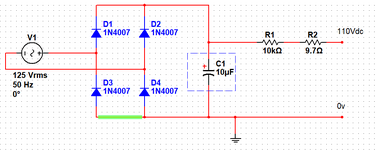
Above is a circuit they put together on some veroboard mounted in a little PCB enclosure.
They have been using a variac to drop 230Vac mains down to about 125Vac for the input of this circuit to give ~110Vdc out.
I put this into Multisim just for visual purposes.
R2 is simulating the coil impedance, and R1 was apparently selected to act as a discharge resistor through the coil when power is disconnected.
The problem our test department is having is the track highlighted in green is vaporising upon power-up.
I am suspecting that R1 should actually be in parallel across the output terminals, but I am puzzled as to why the highlighted track is vaporising.
Any ideas? I feel like I am missing something really obvious here, but I am going to blame Monday morning for this one.
For reference, the coil on the relay is rated 110Vdc, 9.7R, 11mA.
Up until now our test department has been chaining a couple of 30V dual output DC power supplies in series to get the voltage needed but it's not ideal.

Above is a circuit they put together on some veroboard mounted in a little PCB enclosure.
They have been using a variac to drop 230Vac mains down to about 125Vac for the input of this circuit to give ~110Vdc out.
I put this into Multisim just for visual purposes.
R2 is simulating the coil impedance, and R1 was apparently selected to act as a discharge resistor through the coil when power is disconnected.
The problem our test department is having is the track highlighted in green is vaporising upon power-up.
I am suspecting that R1 should actually be in parallel across the output terminals, but I am puzzled as to why the highlighted track is vaporising.
Any ideas? I feel like I am missing something really obvious here, but I am going to blame Monday morning for this one.
For reference, the coil on the relay is rated 110Vdc, 9.7R, 11mA.
