Continue to Site

Eng-Tips is the largest engineering community on the Internet

Intelligent Work Forums for Engineering Professionals

  • Congratulations SDETERS on being selected by the Eng-Tips community for having the most helpful posts in the forums last week. Way to Go!

Air valve on falling main 1

swazimatt

Civil/Environmental
Aug 19, 2009
275
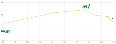
I am reviewing a design of a ww rising main. The pipe is 150mm dia and the pumped flow is in the region of 30 l/s. total rising main is 885m
At the request of the client the discharge location is about 233m past the last high point and about 4.5m below this highpoint (this is the only high point and the WWPS is about 9m below this point). Not my preference but they have their reasons
The pipe will be discharging into the gravity network.
rough profile attached

The designer has placed an airvalve at the high point and i was initially concerned about the flow into the pipe through the air valve every time the pump stops. When the pump finishes a cycle the pipe will drain from the high point to the gravity network. I feel that i might get away without an air valve as the pipe would slowly drain from the open end. As the falling portion of rising main falls less than the rise i do not believe there is the risk of siphoning, but this raises my 2 queries
1. when the pump turns off will the flow in the pipe have enough momentum to create a siphon and continue flow through the system (including the submersible pumps and non return valves)? Is there a way to check this?
2. If i add an AV at the high point i know this will break any siphoning and allow ai into the pipe, but if this exceeds the allowable flow into the pipe will it create negative pressure in the pipe (i doubt it as it is less than 10m(rounded) vertical head) how do i calculate the max rate the pipe would drain? I have tried Hazen williams and find it drains at a max of 31 l/s but not sure if this is correct. I know the AV orifice will restrict flow into the pipe, and "control" the rate of draining, but how / what formulae should i use to calculate this. I have had someone tell me about a similar situation where the air flow through a single air valve resulted in a whistle similar to a steam train every time the pipe drained

thanks
(part of writing this has solved some of my other queries!)
 

Attachments

  • Screenshot 2025-04-02 112142.png
    Screenshot 2025-04-02 112142.png
    24 KB · Views: 18
Replies continue below

Recommended for you

Can you describe this discharge ?
"The pipe will be discharging into the gravity network."
If this discharge is into a liquid flooded pipe or tank, then I see the justification for this air valve.
 
discharging into a manhole with adequately sized gravity network piping - effectively discharging to atmosphere so air will be able to enter from the end of the pipe
 
Last edited:
If you have the air valve, you run the risk of a sewage spill at the air valve. Sewage tends to foul air release valves. There is not much value in having the air valve.

Your pipe is only 150 mm, so the risk of pipe collapse is very small.

The possibility of siphonage is low since there is no opening on the piping end. If you are concerned with siphonage, install a back pressure-sustaining valve on the pipeline discharge end.
the upstream end is open, however it would need to flow through the pumps and non return valves, and as the downstream drop after the high point is about 4.5m less than the upstream side i do not believe there is sufficient drop to create a siphon.

(the engineer in me still wants to know what formula i should use to determine the rate a pipe open at each end would drain)
 
No1. From your sketch I don't think this will syphon, but it is not clear where the water level is in the wet well. As long as it is below the level of the discharge by at least 1m you will not syphon. Unless you have a good non return valve the pipe could reverse flow and syphon the pipe back.

No 2. There will be a negative pressure otherwise air won't enter the pipe, but how much is dependant on the valve size and it's orifice. Yes it will or could whistle.

You haven't said or shown what the normal flow head loss is on your head graph. If it is high enough that your head loss line from the end point is higher than the high point then on re start you will get some two phase flow as the pipe refills.

If it is below the highpoint then you're into slack flow and the pipe will constantly gurgle and flow in an unstable manner.

If you let us know what the discharge head form the pump is it will become clear.

At cessation of flow in essence you have 5m head over your 240m, so just look up flow calculators or tables and see what 2m per 100m flow gives you. Your flow won't/ can't exceed this and will probably be less.
 
1. It appears that your discharge is at a higher elevation than the source, so I cannot see how a siphon can form.

2. The friction pressure drop from the high point to the discharge almost exactly matches the gain in static head between the same two points. This means that under normal operation the pressure in the pipe at the high point will be close to atmospheric. So when the pump stops and the pipe starts draining there will likely be a negative (gauge) pressure at the high point. In this scenario it is probably a good idea to install the air vent / vacuum breaker. The maximum air inflow will be around the 31 litre/second that you have calculated and this gives a velocity of about 15 m/s through a 50 mm vent. An 80 mm vent would definitely be less noisy.

I am not aware of any method to calculate how long the pipe would take to drain if you do not install the high point vent and rely on air ingress from the discharge point. Since the air has to flow counter current to the water flow it will decrease the area available for water flow. My gut feel guestimate is that the pipe will run somewhere between 50% and 75% full and you can base your Hazen-Williams estimate on that to get a ballpark estimate of the draining time.
 
There is probably a way to estimate the time, but the difficulty is knowing if you have a smooth transition between full channel flow and open channel flow.

I suspect not so you will end up with slugging and surging of flow as the air enters in gulps, then the water flows, then slows down then a bit more air goes in etc.

An air valve will be a lot smoother, but you still want to flow at more or less the same velocity so a bigger air valve would be best.
 
Why not put a manhole at the high point and use open-channel flow downstream of that? This would also simplify the design of the lift station because the discharge condition would always be the same.
 
Why not put a manhole at the high point and use open-channel flow downstream of that? This would also simplify the design of the lift station because the discharge condition would always be the same.
this was my first question, but apparently the client wants the discharge from this pipeline at the terminal ww pumpstation
 
There is probably a way to estimate the time, but the difficulty is knowing if you have a smooth transition between full channel flow and open channel flow.

I suspect not so you will end up with slugging and surging of flow as the air enters in gulps, then the water flows, then slows down then a bit more air goes in etc.

An air valve will be a lot smoother, but you still want to flow at more or less the same velocity so a bigger air valve would be best.
this is my worry, if the pump turns on again while the pipe section is draining (from the bottom) it will pump out slugs of compressed air that will "explode" into the discharge manhole and make a real mess.
 
Yup.

When you're dealing with unstable flow, unstable things happen.

Letting it drain from the bottom is not good, but if Katmar is correct and you're only just at atmospheric pressure at the high point when pumping, an air valve could let in sighs of air which died the same thing.
 
No1. From your sketch I don't think this will syphon, but it is not clear where the water level is in the wet well. As long as it is below the level of the discharge by at least 1m you will not syphon. Unless you have a good non return valve the pipe could reverse flow and syphon the pipe back. THE ELEVATION SHOWN AT THE PUMP IS THE PUMP-OFF LEVEL

No 2. There will be a negative pressure otherwise air won't enter the pipe, but how much is dependant on the valve size and it's orifice. Yes it will or could whistle.

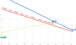
You haven't said or shown what the normal flow head loss is on your head graph. If it is high enough that your head loss line from the end point is higher than the high point then on re start you will get some two phase flow as the pipe refills. I HAVE ASKED THE DESIGNER TO PREPARE THIS GRAPH AS THEY ONLY CALCULATED THE PUMP BASED ON START ELEVATION, AND DISCHARGE ELEVATION IGNORING THE BITS INBETWEEN

If it is below the highpoint then you're into slack flow and the pipe will constantly gurgle and flow in an unstable manner.

If you let us know what the discharge head form the pump is it will become clear.

At cessation of flow in essence you have 5m head over your 240m, so just look up flow calculators or tables and see what 2m per 100m flow gives you. Your flow won't/ can't exceed this and will probably be less.

My next question is:
If the Head graph shows the highpoint is above the head (ie negative head - red line) do we increase the pump head until we have positive preassure throughout the rising main (blue line) with the risk of dischargin to the manhole with a few meters of head (how much head at discharge would be acceptable?)?

or remove the AV, and check that the pump is able to initially pump over the highpoint (red dashed line) and create a siphon flow, the pump should then drop down to the design duty and maintain flow to the discharge location? (this is more an academic question as i see the benefit of including the AV)


< @LittleInch I don't quite understand the last sentence of you response - what am i looking for and what happens if it does exceed the flow?>
 

Attachments

  • Screenshot 2025-04-03 092725.png
    Screenshot 2025-04-03 092725.png
    57.1 KB · Views: 6
Negative head red line is not possible.

Red dashed is better but you'll have slack line/ unstable flow
Blue line is better, but if you don't have a valve adding back pressure then that last 50m will be leaning towards slack line flow as well.

The margins though are really low so it might just work, but as soon as you slow down flow or stop is when you will either drain down or need an air valve.
 
Reverse siphon flow will not be possible as long as the discharge point is above the level at the inlet. Besides, you still got the check valve on pump discharge.
In my experience, gravity flow lines in down flow should have this air valve at the top of the high point - this is to let air INTO the line to make up for the loss of air pushed out at discharge in this 2 phase flow downcomer. Some air will flow in the reverse direction from the open discharge, and the rest of this makeup gets in through this air line at the high point. To minimise air carry under in this downcomer at the discharge, keep line velocity < than that limited by the Froude number of 0.3. There is very little info, as far as I know, in the public domain on hydraulic behaviour of gravity downcomer flow lines when air is flowing in countercurrent to the liquid-air mix being discharged.
 
George,

I the pipe itself can syphon back, i.e. all the water int he pipe downstream the high point could flow back, though in reality air will get in there to destroy the sysphon.

Here's some papers of gravity flow..

What Imeant previously is that your pressure at the high point could very easily fall below atmospheric pressure and start to let air in. Then unless your velocity is > 1m/sec, this air can accumulate and create lots of unstable flow / gushing at the outlet.

I would be really tempted to put a 3m high loop right at the end to give you more height to achieve the blue line head loss. d then get a big of gravity flow dow the pipe into the chamber, but you could put baffles on it to break it up.

Or add a NRV flapper type and put some weights on the flapper...

Pumping over a hill at relatively low heads is not easy.
 

Attachments

  • Designing_Piping_for_Gravity_Flow_-_PD_Hills.pdf
    798.1 KB · Views: 3
  • Flow in horizontal pipe.pdf
    1.1 MB · Views: 3
  • Flow of bubbles in pipes.pdf
    4.1 MB · Views: 3
Last edited:

Part and Inventory Search

Sponsor