PaulKraemer
Electrical
Hi,
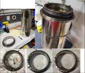
I am working on some registration controls on a printing press where we use an inductive proximity sensor to detect metal targets on a rotary screen coating station. The targets are mounted on an end-ring that holds the screen and has a gear that allows us to drive it. In the following photo, top/left shows an end-ring and a screen prior to assembly. Top right shows an assembled screen with end-ring. Along the bottom are three different end-rings, with five targets, one with three targets, and one with two targets.

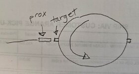
When the screen is installed and rotating, these targets pass in front of the proximity sensor, which is mounted in a fixed position. The following illustration shows how the proximity switch is aimed at the targets ..

The proximity sensor has been installed on this machine for a very long time. We do not know the manufacturer or model number. From its appearance, I believe it is similar to the following Omron part…
https://industrial.omron.eu/en/products/E2E-X1R5C18-2M
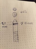
… the sensing range of this Omron part is 1.5 mm (just a little less the 1/16 inch). The operator is able to adjust the sensor position closer to or farther away from the target(s). He generally tries to set the distance just under 1/16 of an inch. If he makes it too close, there is a risk of a target hitting the sensor the sensor. Too far away, and targets may not be detected.
The targets are mounted in precision machined slots on the end-ring that are supposed to be exactly 180 degrees apart (for the two target screen). The targets were also precision machined at some point in time, but I feel like the detection surfaces are not in perfect condition. Maybe over the years, they bumped against the sensor at times and/or they may have been slightly disfigured by careless handling. We have an encoder on the screen motor and controls that allow me to count encoder pulses between detection of the targets. For optimal performance in our application, the number of encoder pulses between each target should be the same. I have seen differences in these counts that make me question the proximity sensor.
Right now, we are running a job with the two target screen. With the proximity sensor in its initial position, we were only detecting one of the two targets. By moving it a little closer, we got it to detect both targets. This makes me believe that there is a very slight difference between the sensor-to-target distance for one target relative to the other. If this distance is different, I wonder if one target causes the sensor to activate a tiny bit earlier than the other.
Not knowing the manufacturer / model number of the proximity sensor we have, I have no clue what its specifications and performance characteristics are. This makes me want to consider changing it.
I am wondering if there is a proximity sensor or other type of sensor anyone here would recommend for this application that would give us the most repeatable turn-on, even if there was a slight difference in distance to one target versus another. For mechanical / space reasons, it would be ideal if we can find something with the same threaded barrel shape with the same diameter as what we have now (which I believe to be 8 mm, based on the M8 designation on the Omron part).
Any suggestions will be greatly appreciated.
Thanks in advance,
Paul
I am working on some registration controls on a printing press where we use an inductive proximity sensor to detect metal targets on a rotary screen coating station. The targets are mounted on an end-ring that holds the screen and has a gear that allows us to drive it. In the following photo, top/left shows an end-ring and a screen prior to assembly. Top right shows an assembled screen with end-ring. Along the bottom are three different end-rings, with five targets, one with three targets, and one with two targets.

When the screen is installed and rotating, these targets pass in front of the proximity sensor, which is mounted in a fixed position. The following illustration shows how the proximity switch is aimed at the targets ..

The proximity sensor has been installed on this machine for a very long time. We do not know the manufacturer or model number. From its appearance, I believe it is similar to the following Omron part…
https://industrial.omron.eu/en/products/E2E-X1R5C18-2M
… the sensing range of this Omron part is 1.5 mm (just a little less the 1/16 inch). The operator is able to adjust the sensor position closer to or farther away from the target(s). He generally tries to set the distance just under 1/16 of an inch. If he makes it too close, there is a risk of a target hitting the sensor the sensor. Too far away, and targets may not be detected.
The targets are mounted in precision machined slots on the end-ring that are supposed to be exactly 180 degrees apart (for the two target screen). The targets were also precision machined at some point in time, but I feel like the detection surfaces are not in perfect condition. Maybe over the years, they bumped against the sensor at times and/or they may have been slightly disfigured by careless handling. We have an encoder on the screen motor and controls that allow me to count encoder pulses between detection of the targets. For optimal performance in our application, the number of encoder pulses between each target should be the same. I have seen differences in these counts that make me question the proximity sensor.
Right now, we are running a job with the two target screen. With the proximity sensor in its initial position, we were only detecting one of the two targets. By moving it a little closer, we got it to detect both targets. This makes me believe that there is a very slight difference between the sensor-to-target distance for one target relative to the other. If this distance is different, I wonder if one target causes the sensor to activate a tiny bit earlier than the other.
Not knowing the manufacturer / model number of the proximity sensor we have, I have no clue what its specifications and performance characteristics are. This makes me want to consider changing it.
I am wondering if there is a proximity sensor or other type of sensor anyone here would recommend for this application that would give us the most repeatable turn-on, even if there was a slight difference in distance to one target versus another. For mechanical / space reasons, it would be ideal if we can find something with the same threaded barrel shape with the same diameter as what we have now (which I believe to be 8 mm, based on the M8 designation on the Omron part).
Any suggestions will be greatly appreciated.
Thanks in advance,
Paul

