Eng-Tips is the largest engineering community on the Internet

Intelligent Work Forums for Engineering Professionals

12" Drain Pipe 2

Status
Not open for further replies.

fyrefreezer

Civil/Environmental
Jul 8, 2022
7
0
0
US
Hello!

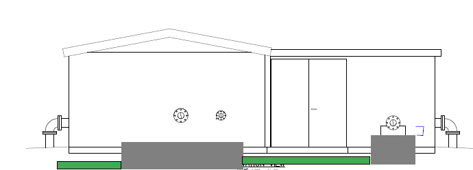
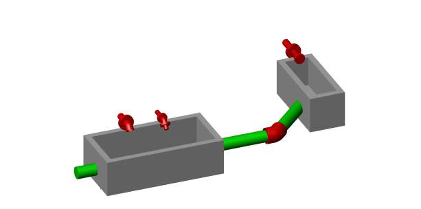
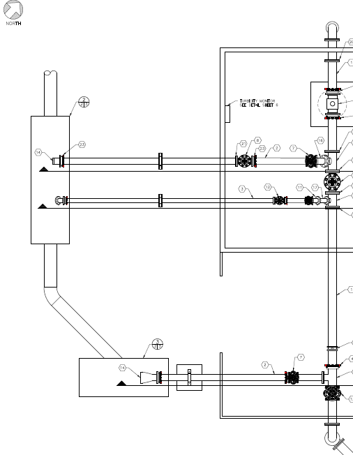
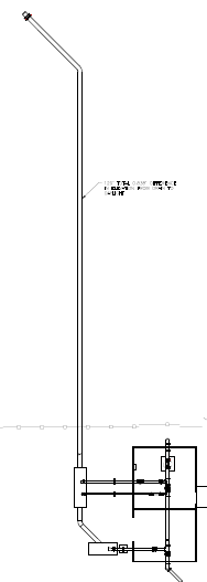
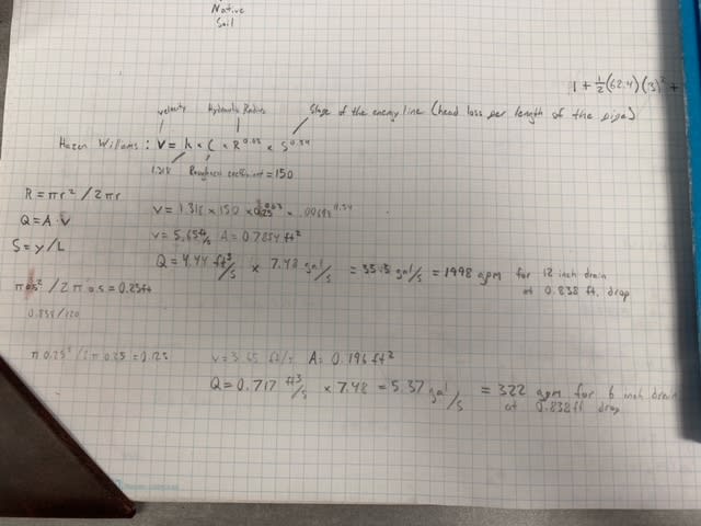
I have a concrete box that is going to be filled with water at 900 gpm, the dimensions are 7' * 5' and a 3' depth. I am planning on installing a 12" drain pipe made of PVC coming from the side of the concrete box, it daylights 120 ft out with only a .838 ft drop (about 10 inches). Will this be able to satisfy the 900 gpm demand without overflowing the concrete box? I used the haze williams equation to find that the 12" inch drain should discharge about 1992 gpm, which would definitely satisfy the 900 gpm demand. If this is wrong in anyway, or have information for a solution, please enlighten me!

Thank you!

hazen_qukygm.jpg
 
Replies continue below

Recommended for you

Designs of this type can sometimes go wrong when you use Hazen-Williams because it is difficult to take the entrance and exit effects into account. But even including those additional losses you should be OK up to about 1400 gpm. Check that your flowrate is steady and does not get to this rate even for short times as you have less than a minute of residence time in the box.

Make sure that the installation is done well with no high or low spots where air or solids could accumulate and increase the resistance. It might be difficult to achieve a constant slope over 120 ft, but that is what you should aim for.

Katmar Software - AioFlo Pipe Hydraulics

"An undefined problem has an infinite number of solutions"
 
This needs a sketch to show sheet this pipe is in the tank.

If there is more out flow than in flow what's the purpose of the box??

Remember - More details = better answers
Also: If you get a response it's polite to respond to it.
 
@LittleInch Using an air gap as means for a backflow preventer, figured a concrete box would be the easiest way to catch the water. Also gives us a little something to help if anything goes wrong.

Only reason I'm worried is we had a similar well outputting 900 gpm with a 12 inch drain that overflowed after starting the well, although that well had a 90 coming from the bottom of the box and a duck bill at the end of the pipe with dimensions of 1' depth x 4' width x 15' length for the concrete box.

@katmar Is there an equation or method that better fits for the entrance and exit effects into account?
 
Using the Darcy-Weisbach equation allows you to model a wide variety of fittings using resistance factors, which are often just termed the K-values because K is the usual symbol used. Try to get hold of a copy of the Crane TP410 manual which is a very good combination of theory and practical advice.

Katmar Software - AioFlo Pipe Hydraulics

"An undefined problem has an infinite number of solutions"
 
it is likely that the pump discharge into the catch basin created a hydraulic jump. that may have exceeded the 3 foot depth. also, if you have air entrainment, that will bulk your flow. i think that you need to make your basin deeper.
 
It looks like your 12" pipe is capable of at least 1500 GPM with that slope when its full of water. But the entry losses might detract from that.
However it will depend on what your maximum height in the tank is allowed to be?? If you can operate at a water depth of say 2'6", then you should have more than enough water height for the flow.

My issue would be what happens as the flow starts as you transition from open channel flow to full pipe flow can get a bit interesting and if you have any high points in your 120ft of pipe you might not be able to flush out all the air.

Also the water coming in needs to be calmed down in such a small box to avoid splashing and creating waves, whilst still creating an air gap.

If the invert of your 122 pipe is at the base of the tank this only gives you two feet of headroom before overflowing which isn't a lot.

Remember - More details = better answers
Also: If you get a response it's polite to respond to it.
 
And avoiding vortexing in the box.

Einstein gave the same test to students every year. Why would he have done that? "Because the answers had changed."
 
Good point. I think it's flowing at about 1m/sec in the 12" pipe so you could easily get a bit of a vortex on the inlet if you're not careful.

I think the biggest risk really is that at 900 gpm, you are possibly / probably not operating on a full pipe and hence you risk the outlet starting to glug or surge if there is any change to the pipe profile from very straight. So you need to check out what the flow is in open channel flow as well as full pipe flow.

Remember - More details = better answers
Also: If you get a response it's polite to respond to it.
 
The "glugs" can induce velocity reductions and even temporary backflow. It could be important to keep the discharge below water level.

Einstein gave the same test to students every year. When asked why he would do something like that, "Because the answers had changed."
 
Here is a little draft I came up with for what I am thinking of. The inverts of both 12" pipes are at the bottom of both basins, water would only be going into one basin or the other not at the same time with a 2.4 inch drop between the connections. I changed the one I was talking about before (the left box) to be a 10' length * 5' width* 5' depth. and the right box to be the original volume of 7' * 5' * 3'. Daylight has been changed to a different position where we get a 1' drop over 120 ft after changing the main box to a 5' depth.

@LittleInch Could you point me in the direction for the needed depth for operation? Why would 2' 6" be a good enough height?


Eng_3_u5ndka.png
Eng_1_buvdis.png

Eng_2_iplkq2.png
eng_4_a6qegg.png
 
minimum head is required to overcome friction and entrance/exit losses. however, you really need to control/account for the hydraulic jump and for bulking caused by air. that will require more than 2.5 feet.
 
I think we got a little off track, I was originally creating a basin with 12" drain coming from the bottom side of the basin, it comes straight out with a constant slope of 10 inches over 120 ft. This basin would have 900 gpm flowing into it from around anywhere from 5 min to an hour. I believe that 12" drain pipe at that slope is good enough for that demand. This box would be for the two pipes on the left that shoot out into the box from a foot high to act as a backflow preventer through means of an air gap.

The most recent post I made was after I made a revision to add a second sump box for the singular pipe outflowing 900 gpm into the box on the right that leads to the original box on the left at a lower elevation. I made the original box larger and deeper to give a little more headroom and to make sure the elevation of the original box is lower than the added box. The added box also has a 12" drain that will lead to the original box and drain from there. Having the added box also will give me more volume in case something goes wrong and the 12" drain is not discharging as expected. Having a deeper box gives me up to 4' of water depth for pressure and still leaving me with a foot of depth in the basin to be safe. I also plan to daylight somewhere else that will give a 1 foot slope over the 120 ft distance.

I was asking on advice for if my assumptions of the 12" drain capabilities were correct or not and if that would lead to needing a larger box size.
 
A flow rate of 900 gpm is 2 cubic ft per second. If the cross section of the box is 5' wide x 4' deep that is 20 ft[sup]2[/sup]. The velocity across the box will be 0.1 ft/second. I cannot see this causing hydraulic jumps or serious aeration. It look like a reasonable design to me.

Katmar Software - AioFlo Pipe Hydraulics

"An undefined problem has an infinite number of solutions"
 
Status
Not open for further replies.
Back
Top