Continue to Site

Eng-Tips is the largest engineering community on the Internet

Intelligent Work Forums for Engineering Professionals

  • Congratulations KootK on being selected by the Eng-Tips community for having the most helpful posts in the forums last week. Way to Go!

15.5 m Cold Formed Girt Design ???

Status
Not open for further replies.

TekEngr

Civil/Environmental
Feb 4, 2012
148
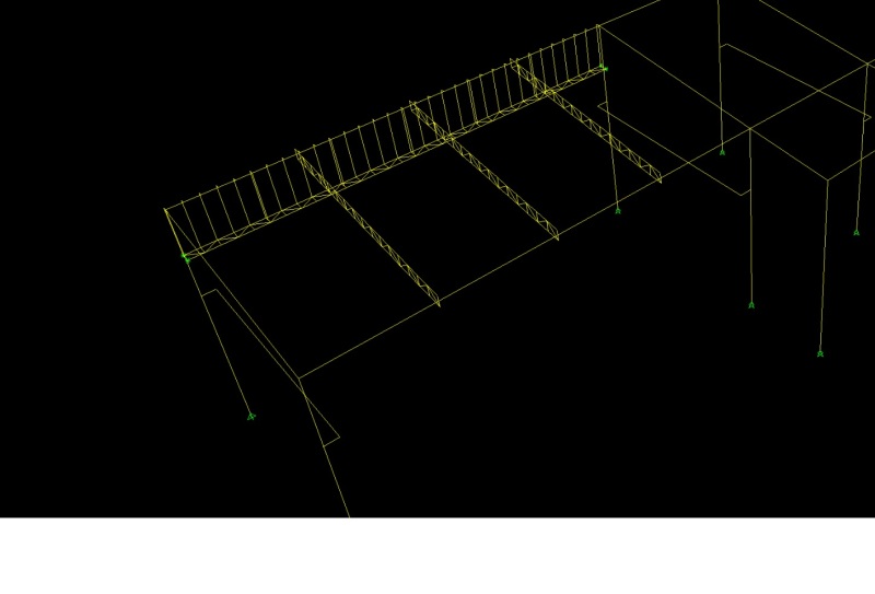
i am designing a PEB shed as shown below , which contain the bay spacing 15.5m and i want to closed the wall upto 2m below from top so my question is that what shape is suitable for the girts design in Cold formed Cee section (maximum Cee section i can use 254-50-1.95).
back to back , double I shape ,Or LGS webbed beam parallel to wind which shape of girt will be better for this type of bay spacing ??
horizontal wind pressure is 1 KN/m^2.
what is horizontal allow able displacement for girts against wind???


[URL unfurl="true"]https://res.cloudinary.com/engineering-com/image/upload/v1454416499/tips/SNAP_SHOT_ieqngf.bmp[/url]
 
Replies continue below

Recommended for you

Normally, single cee shapes are used for girts.

Is there any reason you think you need I shaped girts?

DaveAtkins
 
15.5m is a long girt. All the warehouses I've been in are hot-rolled C-girts with sag rods.

edit: hot-rolled when spans are approaching that level.
 
15.5m equals about 50 ft. in proper units. That is a looooong way.
I would be looking at tube steel or adding some more bays.
 
Sounds to me like you need a few intermediate columns. That will be a challenging wall girt for typical wind loads.
 
I have designed a few cold formed girts in my day. I don't really have a handle of the metric system loading units, but at 15.5m or 50 feet is way to long for a lt guage cold formed girt. I normally try to keep my bays less than 25' or so, otherwise, we will use structural girts.

As others have said, cold formed girts are usually Cees or Zees. With Zees you can nest them together to form a continuous system however, that can turn into a nightmare quickly depending on how you show your grid lines on your plans (you would need to reference outside face of foundation for perimeter grids).
 
With 50' bays, you'd better of looking at bar joist to handle that span. That would be the standard approach for Nucor or NCI in the states anyway.
 
Bar joists for girts? Never seen that.
 
That would be new to me as well.. I would expect a large amount of sag rods in that situation.
 
Maybe he thinks we are taking about purlins?
 
This could be handled with big cold formed girts, probably 350 Z sections lapped. But if you don't have access to those in your country, you need to cut the bay spacing. 250 C sections are just not deep enough.
 
My apology, I was thinking purlin. Its been a while since I've seen the detail, but for girts I recall a post going floor to roof at mid-bay - load from the top of the column had to make it though the roof diaphragm. Doing so allowed for use of cold formed girts.
 
I have seen that as well, along the outside edge of the building having columns at half the spacing of the interior bays to deal with the lateral loading aspects.
 
I agree with Hokie, was about to suggest if your client wants spaghetti girts, he will need at least a Z300 or Z350 double span girts overlapped at each support
 
ameyerrenke and jayrod12 have a point about the girts. A wind post connected to the eaves strut at the top will allow smaller girt sizes to be used. But if you can only get 250 deep purlins where you are, how are you going to build the roof?
 
thanks for your suggestions.
i try this situation in SAP2000 with 325mm deep LGS webbed beam (section used 150-1.55) which will be parallel to the wind direction so horizontal displacement is coming about 130mm does this under the allowable limit however span is 15.5m (50 feet approx)??
to control the vertical sagging of the webbed beam i am providing the HR SHS member as a sag rods (one end of shs member will connect with HR beam and other with Webbed beam) at every 3 m and the sagging will also controlled by the LGS vertical studs as well.
only my confusing part is i assign the support on the top and bottom chord at both end of the webbed beam as you can see the attached picture does this provision correct how i can achieve this connection in practically ???
Webbed_Beam_Option_in_LGS_b8qbsl.jpg
 
150 is a fair bit of deflection but may well be acceptable for shed construction. It implies a five-ish degree rotation in the 2m studs.

From the the screen capture, it's hard to see just how the girt supports are modelled. You'd want at least one support at each end to be able to move freely in the horizontal plane I'd think as you probably want to simulate simple span behavior.

To racooke's point (I think), you'll need to find a way to brace the girt against lateral torsional buckling for the case where the interior chord is in compression (wall suction). Perhaps another line of sag rods inboard of the eave or a moment connection to the sag members that you've got if they're stiff enough to do the job flexurally.

I like to debate structural engineering theory -- a lot. If I challenge you on something, know that I'm doing so because I respect your opinion enough to either change it or adopt it.
 
Status
Not open for further replies.

Part and Inventory Search

Sponsor