Continue to Site

Eng-Tips is the largest engineering community on the Internet

Intelligent Work Forums for Engineering Professionals

  • Congratulations IDS on being selected by the Eng-Tips community for having the most helpful posts in the forums last week. Way to Go!

1MW motor startup cause Turbine Generator to (trip on Differential) why!! 2

Status
Not open for further replies.

newelecteng

Electrical
Apr 8, 2016
64
Hello ALL,

we install new (1Mw 3.3Kv motor DOL) connected to 3.3kv BB when when we try to switch it on. Sometimes especially after long motor shutdown it cause generator differential relay to Pickup and trip the generator. The 87G should be stable even if the mortar draw high stating current.
but after one or two attempt starts of the motor its working ok.

we have same old motors (rating and manufacturer) that working in the plant does not cause this problem

Generator differential relay is BASLER BE1-87G (its pickup 100amp primary). we carry out secondary injection of the relay and its working fine.

Thanks in advance.
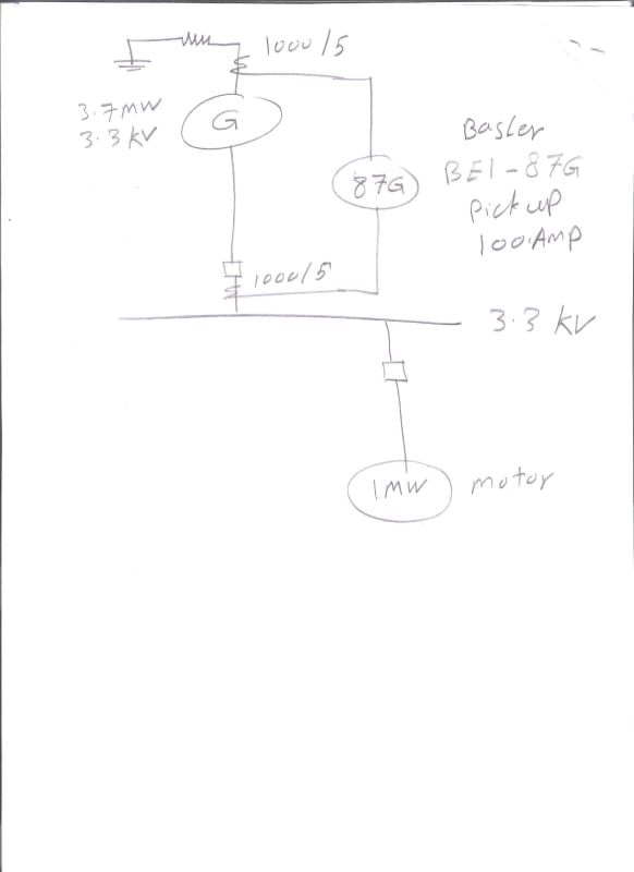
001_lqai80.jpg
 
Replies continue below

Recommended for you

How well matched are the 87G CT's? Is lead length similar or is one set much longer? Have you checked the burden (Inject 5A @ CT block & measure ACV) of CT's and compared?
 
My first guess would be low-accuracy CTs that are creating enough error during motor starting to cause the relay to misoperate. Do you know the relay accuracy class for both sets?
 
As drawn it will trip on load. The CTs have to point in opposite directions, not the same direction.

I’ll see your silver lining and raise you two black clouds. - Protection Operations
 

thermionic1
Gen neutral CT set in much longer that BB CT set.
do you recommend to disconnect 87G relay and inject in CT loop or inject in CT block while relay is connected.
And we have same old motors -rating and manufacturer-(installed in 2001) that dose not make this problem. This issue came with this new motor.

dpc
the relay accuracy class for both sets? C200 for both class with CT winding Resistance: 0.322ohm

davidbeach
CT polarity is ok. This Phenomena just happened sometimes (especially after long motor shutdown). But after one or two attempt starts of the motor its working ok.
 
Could it be that the new motor rated starting current is higher than the old motors which are in service without giving problem (of 87G operation)??
Could it be that the generator is already loaded >2MW when the new motor is started??
Could it be that the original CT sizing calculation / relay setting calculation / stabilising resistor sizing calculation (87G) has not taken the new motor in to account??
 

hi RRaghunath

RRaghunath said:
Could it be that the generator is already loaded >2MW when the new motor is started??

yup sometimes it happen and sometimes is not.

RRaghunath said:
Could it be that the original CT sizing calculation / relay setting calculation / stabilising resistor sizing calculation (87G) has not taken the new motor in to account??

the calculation study has been done many years ago. but this new motor is same as old motors -rating and manufacturer-which they are installed in 2001. and after one or two attempt starts of the motor its working ok.
 
newelecteng -

A CT burden is typically performed with the relay (burden) connected and tested at the terminal block closest to the CT. Lift one lead that goes to CT to isolate. This, of course is all performed with system off line. You should see consistent values from each test at each location. Any significant deviation could indicate a poor / loose connection in the path. Since the Bus and Gen CT leads are different in length you can expect a difference between the two measurements and the settings calculations should accommodate. I've seen cases like this where the lead length / wire size was a limitation.

It would also be prudent to test each CT for ratio, polarity and excitation / saturation. Hire a test company if you don't feel comfortable. Test the relay as well.

Also consider an upgrade to the protection relays. Basler 87G doesn't offer any information like a digital relay would for post fault analysis. A fault record from a digital relay could answer many of the questions you have.
 
thanks thermionic1 for your valuable feedback

thermionic1 said:
Lift one lead that goes to CT to isolate.
what you mean by this "lift one lead ......"
 
When it is running what are the IOP and IRT values?
Do they look right when it’s running?

David may be in something if it like you have it drawn.
 
newelecteng - Lift one of the leads that comes from the CT to the shorting terminal block. The CT will either have 2 (single ratio) or possibly 5 (multi ratio) leads from the CT. The point is you don't want to excite the CT during a Burden measurement so you want the CT isolated for the test by lifting 1 lead so the path to the CT is open. If you have a wiring diagram of the CT circuits it might be easier to explain.

Palletjack - This Basler 87G relay is a 20+ year old design and is more of a static / solid state relay than a digital one, so Iop/Irst are not available nor are any event reports / oscillography, hence my recommendation for an upgrade. These relays utilize the old GE electromechanical cases and test paddles, which in the hands of someone less experienced can be very dangerous to work with (open CT possibility). It's be over 25 years since I've laid hands on a Basler, but I believe this to be the case.
 
This maybe a stupid question, but if the trips occur after a long shutdown period, are your space heaters in the motor working? Could be moisture accumulating and causing ground currents.
 
djs said:
Could be moisture accumulating and causing ground currents.
even we have ground faults in the motor the Gen. Diff. relay should be stable because it outside the differential zone.
 
Status
Not open for further replies.

Part and Inventory Search

Sponsor