Eng-Tips is the largest engineering community on the Internet

Intelligent Work Forums for Engineering Professionals

200ftx200ft PEMB Foundation Design 2

Status
Not open for further replies.

NA110

Structural
Jun 28, 2024
7
0
0
US
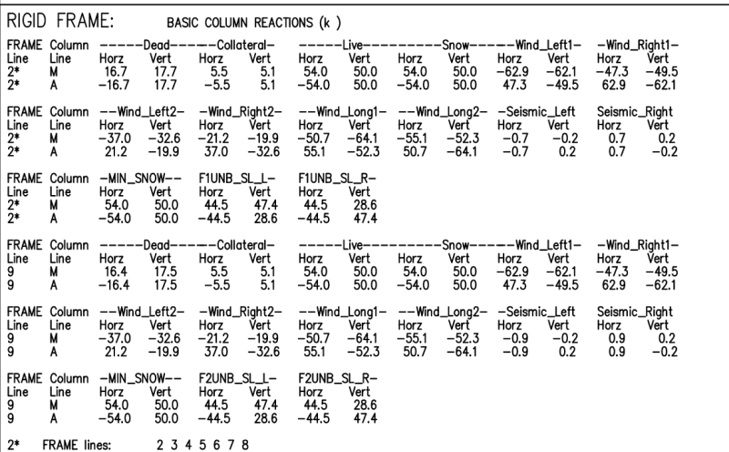
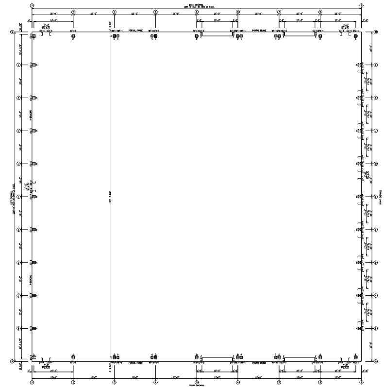
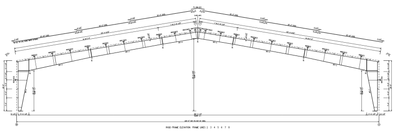
Recently, I have been awarded a project to design the foundation for a 200 ft x 200 ft x 28 ft tall pre-engineered metal building (PEMB). Can anyone guide me on the suitable type of foundation for this large PEMB? The frame spacing is 25 ft center-to-center. Initially, I was considering a spread footing with piers and grade beams, tying the columns in both directions with pedestal columns and grade beams. However, the client wants to minimize costs and prefers a slab on grade with haunches. Is a slab on grade with haunches suitable for this type of large PEMB? Please, can anyone guide me on this?
 
Replies continue below

Recommended for you

There has been a lot of discussion on here over the years about PEMB foundation types. Hairpins used to be very common in cheap medium to small buildings, where tie rods were used to resist bigger loads. Ideally if you can design reasonably sized footings to resist the loads that is easiest.
 
Unfortunately there isn't enough information to offer any project advice here.

1. What are the soils at the project side, is excavation an issue?
2. What magnitude are the thrust loads, Can you provide a rough loading?
3. Are the soils expansive?
4. What loading will be on the slab inside, ie forklifts, racking etc.?
5. What kind of wind loading (Vult)?
6. Are there interior columns - if so this reduces horizontal thrust?
7. Is there a geotech report, if so, are there any conditions that require minimum sizes/depths etc.

You will most likely find that gravity loading on soil will not control, these designs are almost always controlled by uplift. Therefore as others have said here, burying your foundation and utilizing the soil on top (normally I place top of footing at a minimum of 3' below finished grade for PEMB) will provide you the least amount of concrete. Laterally, tie beams are typically used (especially if this is clear span for this size structure) when the loading requires such loads. A slab on grade can maybe get you 10 kips with hairpins, maybe more if reinforced all the way across where the slab acts as your tie beam. I'm not a big fan or using the slab on grade for more than 10 kips. I also like to do perimeter tie beams at the braced frames to counteract the thrust loading along the length of the building.
 
Here is the layout and reactions of the PEMB
reactions_pe8j1l.png

Sketch_mltd4p.png

and the loading will be from telehandler. unladen wt = 67000lbs with a lifting capacity of 28000 lb
 
So...what's the largest PEMB foundation you have personally designed, and what's the largest that has been designed by anyone else in your office?
 
@phamENG: I think your question doesn't relate with my query. but still I designed approx 100ft x 100ft with the same slab with hunched
 
It relates to wondering if you're qualified to design it. Joining a forum and, for your first post, saying "I was awarded this design...can anyone tell me how to do it?" (paraphrasing, of course) doesn't instill confidence. But if you've designed a 10,000sf metal building system foundation, then you should be able to do this one.

Every client wants to reduce costs. In my experience, most buyers of a metal building system will gladly compromise on safety if it saves them a buck and they can pass the risk off to an engineer. Not all, of course, but most that I've dealt with fall squarely in that category. This is a big building. You can design everything to stay in the slab, but it won't be cheap. I usually tell my clients when they're considering a MBS to keep in mind that they'll likely spend between 150% and 200% of traditional foundation costs for a properly designed MBS foundation.

I will say that the detail you posted in that image is laughably inadequate for most MBS foundations, even small ones, unless you have a lot of additional detailing shown elsewhere.

So just design the foundation, follow the numbers, and give them the design that they need - not necessarily the one that they want.
 
I hate the outputs of these PEMB programs. Very hard to follow and there is not enough diagrams. They only show diagram one axis only. Took me a while to figure the lateral load of the end walls (Column at line 1 and 9). Good luck to you! Also you have pretty big horizontal reactions from snow and dead load! On all of the PEMBs I have done, I only get large horizontal reactions from wind. What does this thing look like elevation wise?? The columns are tilted?
 
@phamENG : Please read my post again. I didn't say, "Can anyone tell me how to do it?" I simply shared my opinion and asked for guidance on whether my approach is right or not. I believe it's not appropriate for you to say that I am not qualified to design it. This is my first time posting, and it's frustrating to encounter someone who misreads my post and judges me
 
@NA110 - pham is just saying that based on the wording that is how you came off, I read it similarly at first.

Now to your design. I input some of those loads into a spreadsheet I have and not knowing more information about your foundation, ie thickness and how deep you have it, I cannot offer an opion other than your 9' square footing is very inadequate if this is a turndown footing and not centered under the column and buried at least 3' deep to top of footing. Uplift only, not including any increase for prelim loading I am larger than a 9' square x 24" thick at a depth to top of 3' assuming 110 soil density and accounting of a 0.6 factor in resisting dead load (including foundation weight) while including a triangular soil area above as resisting weight based on depth to top of footing. I also didn't look to see if there are braced frames along that line that may impact foundation design. That being said, if you are using an offset footing with this kind of loading, I suspect you will be a factor of 4 min times larger than a foundation centered under the column due to overturning moment induced, even with uplift loading. Based on your horizontal reactions, you will most likely need tie beams. If this were my project, I would have spread foundations, pedestals top top of slab and tie beams and wouldn't even try another system for something this large (other than maybe caissons if the geotech recommended them).
 
yeah, that gravity loads put a lot of thrust! Definitely cannot rely on slab and hairpin. I have never done one this span before. Your horizontal outward forces are huge! Good luck.
 
Never said you weren't. Said your question was a little vague and made me wonder. I also said that you should be able to do this. We're engineers. Making judgements is what we do. This is a big building with a lot of risk involved, particularly during erection. For consequential matters, I don't like giving out advice unless I'm confident the recipient is capable of using it.

The turndown of the slab has little to do with the resistance of loads from the superstructure unless you specifically detail them to participate. The footings under the frames do, whether they are integral with the slab or not. If you make them integral with the slab, how big are they? How are you resisting the thrust? How does it compare it the method you wanted to do? You should be able to work up some quick order-of-magnitude estimates and see which one is more economical considering quantity of materials, complexity of detailing, excavation, etc.
 
Aesur said:
Based on your horizontal reactions, you will most likely need tie beams. If this were my project, I would have spread foundations, pedestals top top of slab and tie beams and wouldn't even try another system for something this large

You would use tie beams every grid 250 ft long(2-8)? Don't you think at some point there is enough dead load to resist the sliding that you don't need to tie them to other side? I was just thinking out loud.
 
DoubleStud said:
You would use tie beams every grid 250 ft long(2-8)? Don't you think at some point there is enough dead load to resist the sliding that you don't need to tie them to other side? I was just thinking out loud.

Correct, I would have tie beams across the whole building. with PEMB and probably a thin slab, no I don't think there is enough weight to resist that kind of thrust loading. remember this thrust occurs at 25' o.c., so you have a 25' long strip of concrete by say 5" thick x 250' long which is 390.6 kips weight, now apply 0.6 factor and a 0.35 friction coefficient and you can resist 82 kips thrust, but you have thrust each end in opposite directions, so if not tieing teogether with a tie beam you get half each side, so 41 kips resistance. This doesn't even cover thrust from the live load alone.

This is also why I argue that many restrained retaining walls are improperly designs if you look at the actual force at the restraint and what you really have to restrain it.
 
DoubleStud - 200' I think, but yes, I certainly would. At that length you have to start looking closely at elongation, but you still need it. What happens when, 2 years from now, they decide they need a bathroom and cut a trench in the slab for plumbing across 12 of the frames, cutting loose the dead weight anchor you're relying on? Bye-bye building. At least with a tie beam below the slab, it gets pretty obvious that they're cutting something they shouldn't be. One time, I saw a MBS that was put up, relying on hairpins in the slab, that was built without the slab to make tenant build out easier. All the hairpins were bent vertical. Yikes.
 
Status
Not open for further replies.
Back
Top