PaulKraemer
Electrical
Hi,
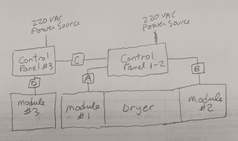
I am working on a project for which my company will be providing a small machine that will perform a particular function. The controls for this machine will be located in a dedicated control panel that will not be mounted directly on the machine. A limited number of wires and cables will be required to connect the Control Panel to the machine. The intention is for the Control Panel to remain in a single location, but for the machine to be disconnected and removed when it is not in use.
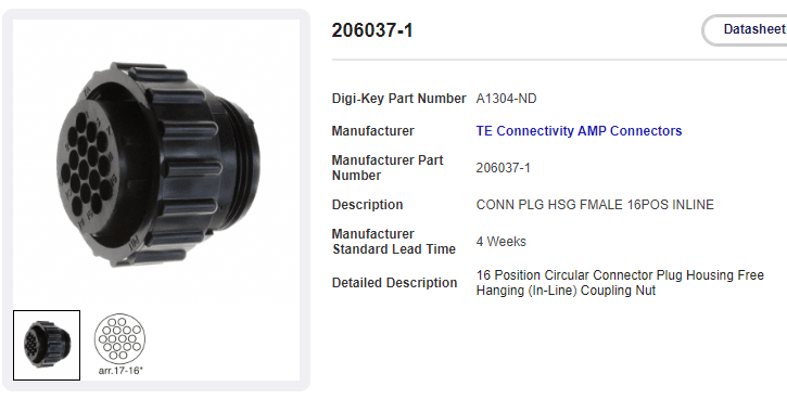
For this reason, I would like to use multi-pin connectors at one end or the other for all of my interconnect wires and cables with the goal being to make the disconnection/separation of the Machine from the Control Panel as easy as possible. One of my interconnect cables will be for the power connection from a VFD to an AC induction motor. As this is a higher power / more likely to create noise connection, my plan is to run this cable all by itself. I've already received some good suggestions on this forum regarding the types of connectors I can use.
The remaining wires and cables that have to go from the Control Panel to the Machine are as follows:
(1) Two wires used to energize the 24 VDC coil of contactor (specs list the coil inrush power as 5.4W and the hold in power also at 5.4W
(2) Two wires used to energize the 120 VAC coil of a contactor (specs list the coil inrush power as 70 VA and the hold-in power at 7.5 VA
(3) Three wires used to engerize 24 VDC PLC inputs
(4) One three conductor shielded cable that provides frequency feedback (5 VDC signal) from a ring-kit speed sensor mounted on a motor)
Both of the contactors I mentioned in (1) and (2) above remain energized at all times while the equipment is in operation, and are only de-energized if someone hits an E-Stop pushbutton. (So these contactors do not switch ON and OFF during normal operation).
My gut feeling is that I most likely would not have a problem if I was to run all the above wires and cables ((1) - (4) above) through a single 3/4 inch liquid tight conduit and terminating them all on the same multi-pin connector.
I am just wondering if anyone here can tell me if my gut feeling might be wrong, or if there are any applicable codes that would make this a inadvisable. This equipment will be going to California. I am not specifically required to get it UL certified or CE marked, but when possible, I try to do my best to comply with these standards.
Any advice will be greatly appreciated.
Thanks in advance,
Paul
I am working on a project for which my company will be providing a small machine that will perform a particular function. The controls for this machine will be located in a dedicated control panel that will not be mounted directly on the machine. A limited number of wires and cables will be required to connect the Control Panel to the machine. The intention is for the Control Panel to remain in a single location, but for the machine to be disconnected and removed when it is not in use.
For this reason, I would like to use multi-pin connectors at one end or the other for all of my interconnect wires and cables with the goal being to make the disconnection/separation of the Machine from the Control Panel as easy as possible. One of my interconnect cables will be for the power connection from a VFD to an AC induction motor. As this is a higher power / more likely to create noise connection, my plan is to run this cable all by itself. I've already received some good suggestions on this forum regarding the types of connectors I can use.
The remaining wires and cables that have to go from the Control Panel to the Machine are as follows:
(1) Two wires used to energize the 24 VDC coil of contactor (specs list the coil inrush power as 5.4W and the hold in power also at 5.4W
(2) Two wires used to energize the 120 VAC coil of a contactor (specs list the coil inrush power as 70 VA and the hold-in power at 7.5 VA
(3) Three wires used to engerize 24 VDC PLC inputs
(4) One three conductor shielded cable that provides frequency feedback (5 VDC signal) from a ring-kit speed sensor mounted on a motor)
Both of the contactors I mentioned in (1) and (2) above remain energized at all times while the equipment is in operation, and are only de-energized if someone hits an E-Stop pushbutton. (So these contactors do not switch ON and OFF during normal operation).
My gut feeling is that I most likely would not have a problem if I was to run all the above wires and cables ((1) - (4) above) through a single 3/4 inch liquid tight conduit and terminating them all on the same multi-pin connector.
I am just wondering if anyone here can tell me if my gut feeling might be wrong, or if there are any applicable codes that would make this a inadvisable. This equipment will be going to California. I am not specifically required to get it UL certified or CE marked, but when possible, I try to do my best to comply with these standards.
Any advice will be greatly appreciated.
Thanks in advance,
Paul