Continue to Site

Eng-Tips is the largest engineering community on the Internet

Intelligent Work Forums for Engineering Professionals

  • Congratulations waross on being selected by the Eng-Tips community for having the most helpful posts in the forums last week. Way to Go!

2D Frame Analysis 4

Status
Not open for further replies.
Replies continue below

Recommended for you

For initial estimates? I'd probably just look at it as a portal frame and "smooth" the loads to uniform distributed loads. Then you could break out the moment at each joint to estimate the knee brace loads.

For actual design? Rigorous analysis.

But if you don't have a back of the napkin method yet...I'd advise you to do the rigorous analysis first and then play with some shortened versions and see what comes close.
 
Even for a prelim design (unless meatball), I'd run it through a 2 or 3-D frame program... about 5 minutes work... and then play with it if neccessary.

Rather than think climate change and the corona virus as science, think of it as the wrath of God. Feel any better?

-Dik
 
1. Remove three redundant members (horizontal member under ridge + sloping member at each knee).
2. Create 3 hinged arch by pinning ridge node.
3. Solve determinate structure for applied loads.
4. Calculate horizontal deflection between end nodes of member below ridge (unit load method).
5. Calculate force in horizontal member below ridge, assuming pinned ends.
6. Revise M[sub]knee[/sub] to account for F[sub]hor[/sub]
7. Calculate force in redundant members at knee, assuming pin ends. F[sub]diag[/sub] = M[sub]knee[/sub]/offset distance

BA
 
I'm with Dik. Run it in a frame program. Gravity and lateral loads, knee brace, point loads. There's no reason to burn brain energy and paper on that one (even though that is what the OG question was). Your practice is (probably) also paying a subscription fee for some sort of frame analysis software, so make it work for you.
 
Looks like the OP isn't interested in pursuing the question, so I may be wasting my time, but another approach is to find a source of similar frames and get an approximate idea of what to expect (without the redundant members).

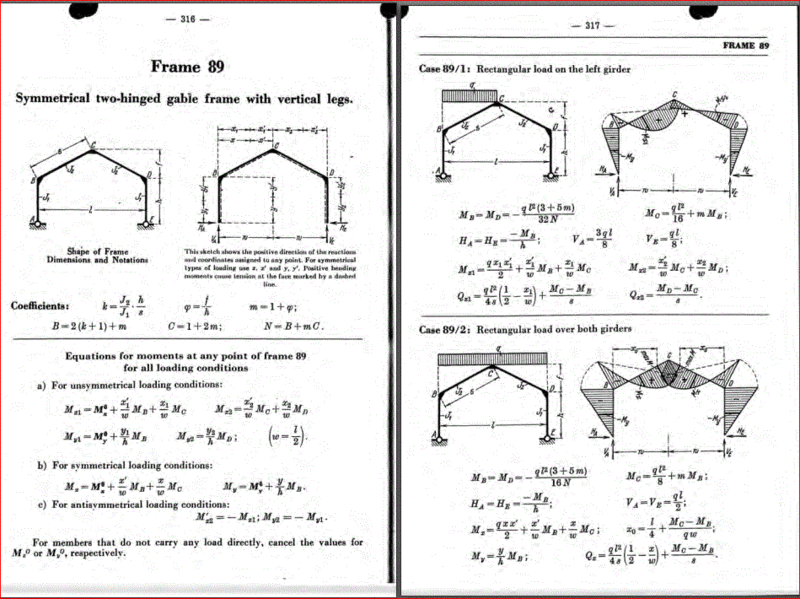
I would consider gravity loads and wind loads separately. First, the gravity load. Excerpts from Kleinlogel are shown below.

Capture_f2cyow.gif


Next, wind load. Notice that wind affects all of the surfaces of the building, not just the windward wall. Also, load combinations do not usually consider all loads together. When wind is blowing, snow is not as heavy, etc.

Capture01_p6hzvc.gif


Additional bracing members may be included after studying the rigid frame without them. I am guessing they are not needed, but fixed or semi-rigid supports at the base could be helpful.

BA
 
BAretired: Thanks for the reference, I will be sure to chase down a copy. I'm a big fan of hand methods and I have noticed you have quite the knack for approximate hand analysis. I would kill to be able to spot compatibility constraints even half as well as you. If you ever have other references you feel like sharing on this topic know they will not go to waste. Please share!
 
Thanks for the compliment, Enable. I like hand methods too, particularly for preliminary analysis. The name of the book is "Rigid Frame Formulas" by A. Kleinlogel. It was translated from German, so some of the symbols are a little different than we are used to in North America. I believe it is currently available for download on the internet.

Capture_doqror.gif


BA
 
You're welcome, phamEng. It was once the structural engineer's go-to document for frame analysis; that has largely been replaced by frame programs. Neither should be used without a sanity check; print errors and computer errors are birds of a feather.

BA
 
Hi
I would do a quick model in a FEM-software. Model one half and then mirror the model.

I actually did just that and realized that the geometry is probably incorrect. The top starts at (0,12) goes to (7,14) and then finishes at (13,16). That means that for the first 2 ft height increase the horizontal span is 7 ft but for the second 2 ft the horizontal span is 6 ft. So the top beam is not straight, or the measurements are incorrect.

But it also looks like the OP has lost interest in this when I look at the dates for the posts.

Thomas
 
Status
Not open for further replies.

Part and Inventory Search

Sponsor