Eng-Tips is the largest engineering community on the Internet

Intelligent Work Forums for Engineering Professionals

  • Congratulations waross on being selected by the Eng-Tips community for having the most helpful posts in the forums last week. Way to Go!

2D - Geometrical Tolerance 3

Status
Not open for further replies.

CAD2015

Computer
Jan 21, 2006
1,932
US
Hi,

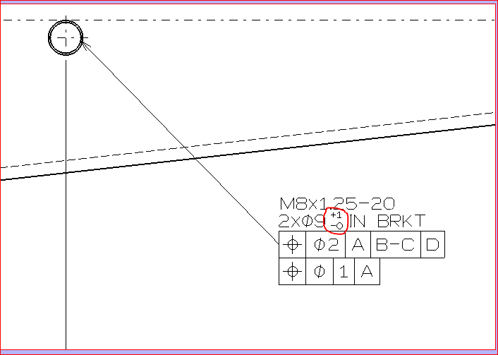
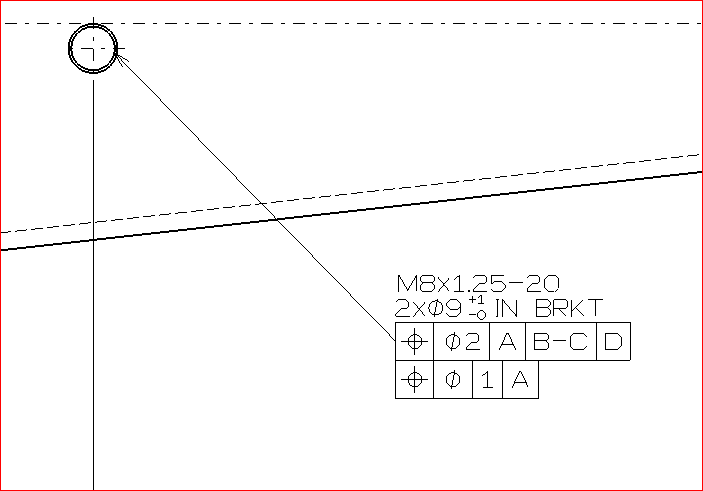
Is it possible to create the feature (Geometrical Tolerance) shown in the picture below of one (without adding another Geometrical Tolerance)?
image_szzyt0.png


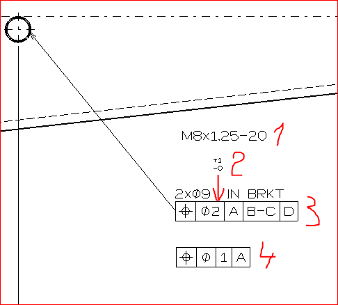
I have created it using 4 different elements:
1) - Text
2) - Text
3) - Geometrical Tolerance
4) - Geometrical Tolerance
image_zmg7m4.png


Thanks

CAD 2015
 
Replies continue below

Recommended for you

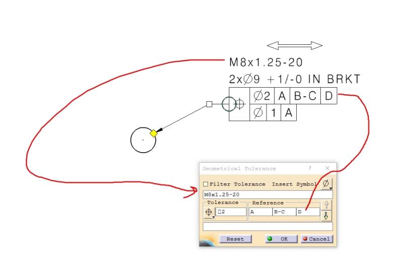
For Top Line of text and GDT:
181127_Image025_kxxvhc.jpg

--------------------------------------------------------------------------------------------------------
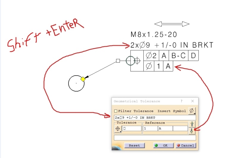
For Bottom Lines down arrow for GDT and shift + enter for 2nd line of text:
181128_Image021_m7wnen.jpg
 
RychiT,
Thanks for your prompt reply.
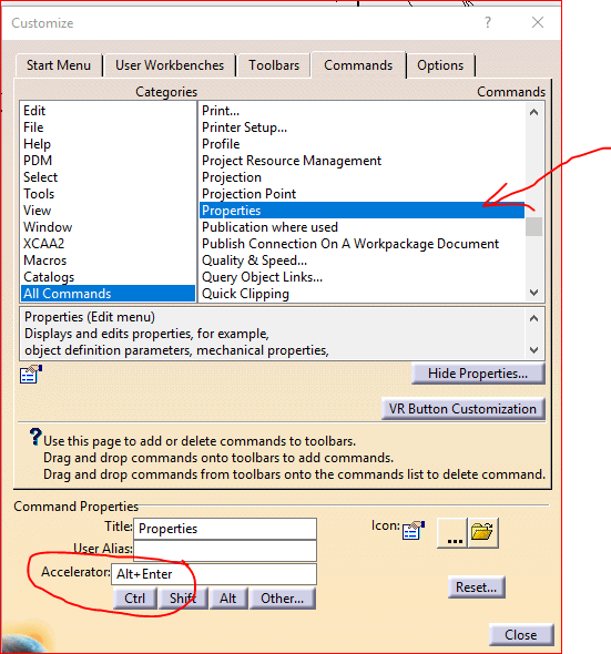
I am not sure how to follow your directions, Alt+Enter open the Properties tab............[mad]

image_bnpcwi.png


CAD 2015
 
SHIFT+ENTER when in text box create an hidden /n character to go to next line

2018-11-28_18-56-11_snftql.png


Eric N.
indocti discant et ament meminisse periti
 
I went back and corrected my post.
Shift+Enter will bring you to the next line the text editor as well.
I had Alt+enter on my mind for some reason!
 
No worries, RickyT.
Thanks for your contribution.

CAD 2015
 
There is another question related to this thread.
Please, have a look at the picture below:


image_b8kbtg.png


How should we add the +1/-0 value(red circled) in the same way that is shown in the picture (overlaid)? We know that this value should have smaller size.


Thanks!


CAD 2015
 
ok I am not sure going with Annotation texts is the best solution as the definition of sub text properties in annotation text is hard to get.

if you want associative dimensions I would suggest you create:


the M8 dimension

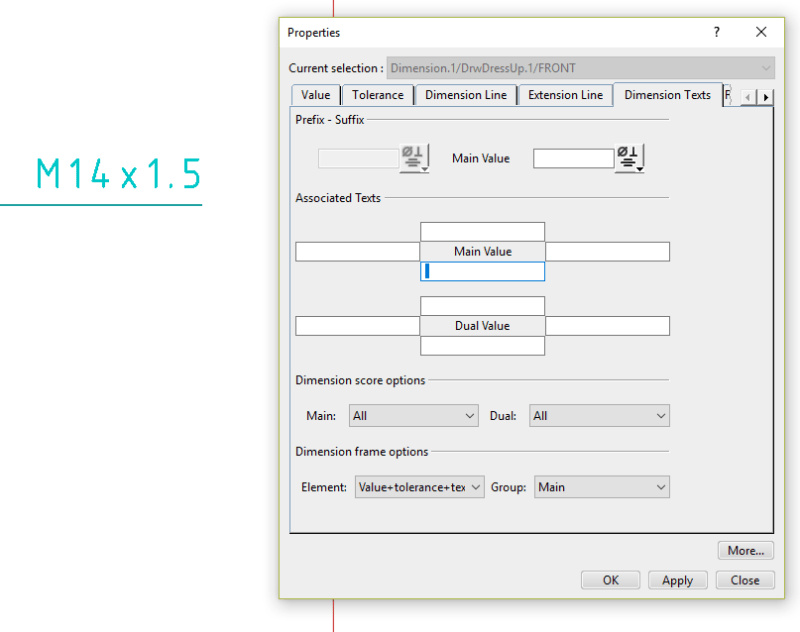
edit the dimension and add a <space> to the lower text:

2018-12-02_13-03-35_qsbmce.png


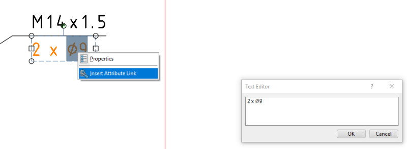
then the 2xø9 text

locate the text over the <space> created in step 1
link position of text to dim1

edit text and select "ø9" in the drawing not the GUI, go RightClick : insert attribut link, select the 3D feature to get the real "ø9" so text value is linked with 3D feature.

2018-12-02_13-11-32_cgb40h.png


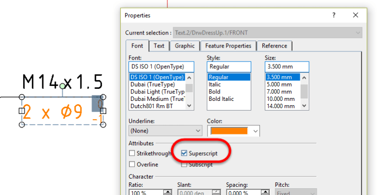
Then add tolerance as text <space>0-1
select <space>0 , in text property select Superscript
select -1 , in text property select Subscript

you need to have <space> and "0" as superscript if you want the digits (0 and 1) to align

2018-12-02_13-13-50_wiregq.png


Finally double Annotation to dim 1

it will be place automatically below the text as catia knows there is a sub text (the <space> added in step 1)


Hope this help


Eric N.
indocti discant et ament meminisse periti
 
Itsmyjob,

Thanks for this last reply.
I will try to follow your directions.
However, your reply has already very interesting info.
Thanks a lot!

CAD 2015
 
I would keep them separate. Dimension the hole first so that it updates to the 3D model of the hole and then add the GD&T box onto that dimension. This provides the most update-ability of the drawing to the 3D CAD.
 
Status
Not open for further replies.

Part and Inventory Search

Sponsor

Back
Top