Navigation
Install the app
How to install the app on iOS
Follow along with the video below to see how to install our site as a web app on your home screen.
Note: This feature may not be available in some browsers.
More options
Style variation
-
Congratulations TugboatEng on being selected by the Eng-Tips community for having the most helpful posts in the forums last week. Way to Go!
You are using an out of date browser. It may not display this or other websites correctly.
You should upgrade or use an alternative browser.
You should upgrade or use an alternative browser.
2D Point Chart 3
- Thread starter CAD2015
- Start date
- Status
- Not open for further replies.
-
1
- #2
Hi
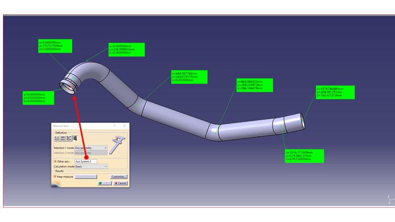
Your chart seems (for me) to be with values get from a local system axis reference.
Your measure in 3D seems to be with the product system axis reference, which is something else...
Make active the part, select the point and transform the point in point with coordinates.
Regards
Fernando
- Romania
- EU
- Thread starter
- #3
Thanks Ferdo.
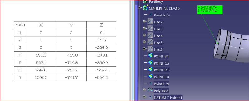
Yes, the previous designer used an Axis System, placed on the given values of the point shown on the right picture.
However, using that Axis as reference, the values in the left Chart are a lot different.

I will review this task accordingly.
Thanks a lot for your prompt answer!
![[2thumbsup] [2thumbsup] [2thumbsup]](/data/assets/smilies/2thumbsup.gif)
CAD 2015
Yes, the previous designer used an Axis System, placed on the given values of the point shown on the right picture.
However, using that Axis as reference, the values in the left Chart are a lot different.

I will review this task accordingly.
Thanks a lot for your prompt answer!
![[2thumbsup] [2thumbsup] [2thumbsup]](/data/assets/smilies/2thumbsup.gif)
CAD 2015
CAD2015; to orient the pipe to match the point coordinates, you will have to do the Point-Point transformation 3 times. You can use any 3 points in the chart, but I suggest spreading them out for the most accuracy and using points #1, #4 and #7.
The chart coordinates have been rounded off, so let us know if that causes problems for you.
The chart coordinates have been rounded off, so let us know if that causes problems for you.
- Thread starter
- #5
-
1
- #6
in drafting you can use the Coordinate table and give the Axis system you want as reference for the XYZ values.
if you don't use any you will get part coordinate system, if you use the axis used by the previous designer you should get the same values.
if you want to rebuild the axis used for the table please follow the steps:
create lineZ point1 point4
create planeXY normal to lineZ at point1
create projectP4 of point4 on planeXY
centered on point1 on planeXY, create circle1 radius = point4.X
centered on projectP4 on planexy create circle2 radius = point4.Y
create circle intersections i1,i2
create axis origine on point1
Z direction define by point4 (check invert as point4.Z <0 )
now you have to define X direction by selecting i1
check point coord in new axissystem, if not good, define X direction selecting i2
have fun
Eric N.
indocti discant et ament meminisse periti
indocti discant et ament meminisse periti
-
1
- #7
- Status
- Not open for further replies.
Similar threads
- Replies
- 3
- Views
- 2K
- Question
- Replies
- 3
- Views
- 2K
- Replies
- 4
- Views
- 2K
- Replies
- 1
- Views
- 1K
- Replies
- 3
- Views
- 516


![[neutral] [neutral] [neutral]](/data/assets/smilies/neutral.gif)
![[thumbsdown] [thumbsdown] [thumbsdown]](/data/assets/smilies/thumbsdown.gif)