Continue to Site

Eng-Tips is the largest engineering community on the Internet

Intelligent Work Forums for Engineering Professionals

  • Congratulations IDS on being selected by the Eng-Tips community for having the most helpful posts in the forums last week. Way to Go!

2D Views.............. 2

Status
Not open for further replies.

CAD2015

Computer
Jan 21, 2006
1,962
Hi,

My new assignment is a 2D file notes and Title Block updates.
But I found something uncommon: all the views have the same name “Isometric view”.
I am very puzzled. Never saw something like that!
All the views are independent of each other.
I even created another Isometric view, identical with one created by the previous user.
Just for curiosity......
Now, I know how he created these views:
1. Selected from 2D Isometric view option
2. Select Top(or a main view) in 3 D and pick up a planar face of the solid
3. Place the view back in the 2D file


Please, let me know if I am an ignorant and I miss something from Catia!............
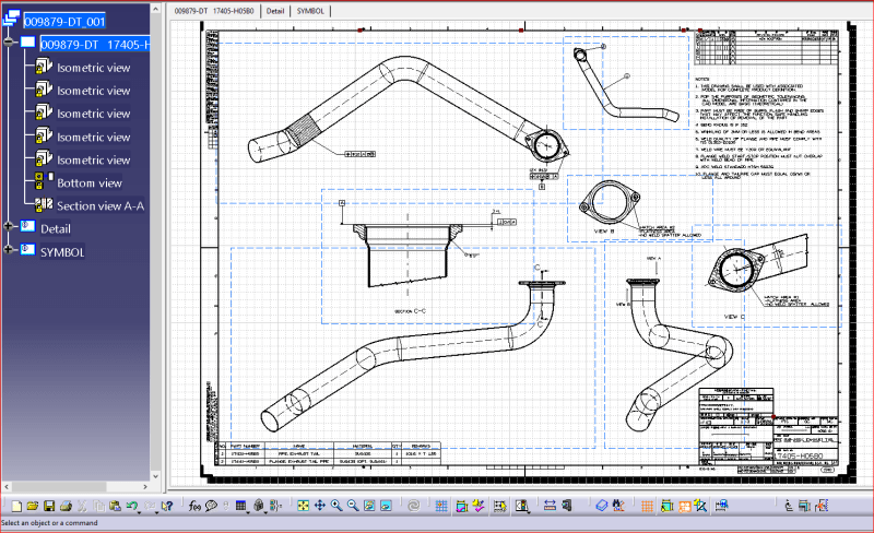

image_rjqtpg.png


I placed the 3D picture of the model, just for evidence:


image_oa3bbw.png


What do you think about this?
CAD 2015
 
Replies continue below

Recommended for you

Normally, there is a Front View and Top View, Side View on most drawings (depending of course on how complex the drawing is) The Isometric view (not necessarily a true isometric; just a 3D view) are added at the end near the bottom of the tree.

Since you didn't show the complete drawing, I can't really comment on good or bad. But it is strange, at least to me. Are the views labeled on the drawing to describe what each view represents?

(maybe be drafter doesn't know any other way to create views?)
 
Thanks JackK,
I will place a detailed reply tomorrow morning.

Regards,

CAD 2015
 
JackK,

I have updated my thread.......
It is very strange; actually, it is a lot easier to add -like you specified- Front View and Top View, Side View.
That's way I am so puzzled!
What do you think?

CAD 2015
 
Thanks for revising the original post to include the entire drawing, as well as the image of the model.

I think the drawing makes sense, with the primary views and auxiliary views. So I don't see any problems there.

I think we both agree that it is much easier in CATIA to just create the Front view and then project views from there. But apparently the drafter of this drawing either didn't know or felt that Isometric views were the way to go.

Going forward, I guess you have 3 options if you are taking ownership of this drawing:
1. leave it like it is (and put the other guys name in the titleblock)
2. rename the isometric views so you (and everyone else who has to work with this drawing) know which view is which in the list
3. delete the isometric views and make all new views and new dimensions

Personally, I would go with option #2
 
I would also label that view to the left of the notes. Is that the Bottom View?

And I think Section View A-A in the tree is actually section C-C on the drawing, so that should be renamed.
 
Sharp eyes, JackK!
You're right!

The main reason I asked a second opinion in this matter is because some people act very possessive when it comes about their "baby" (their creation).
They fight to prove that they were right and invoke different reason in defending their way of design!
To me, the way the tree views have been created is completely wrong......

CAD 2015
 
It is preferred to have the views align with each other, the 3 main views do not.
The 2 "view in direction" views look like they are not in the correct orientation either (about 90° off).
Due to the low number of dimensions, I would recreate all the views.
Hard to see all the detail on a screen shot, but these views do not follow basic 1st or 3rd angle projection.

 
I have attached the CATIA Drawing file.
RickK, can you add more details about your last statement:

"Hard to see all the detail on a screen shot, but these views do not follow basic 1st or 3rd angle projection."

Thanks!
 
Status
Not open for further replies.

Part and Inventory Search

Sponsor