Continue to Site

Eng-Tips is the largest engineering community on the Internet

Intelligent Work Forums for Engineering Professionals

  • Congratulations Danlap on being selected by the Eng-Tips community for having the most helpful posts in the forums last week. Way to Go!

2meter cantilever slab + beam design

Status
Not open for further replies.

kellez

Civil/Environmental
Nov 5, 2011
276
Hello everyone,

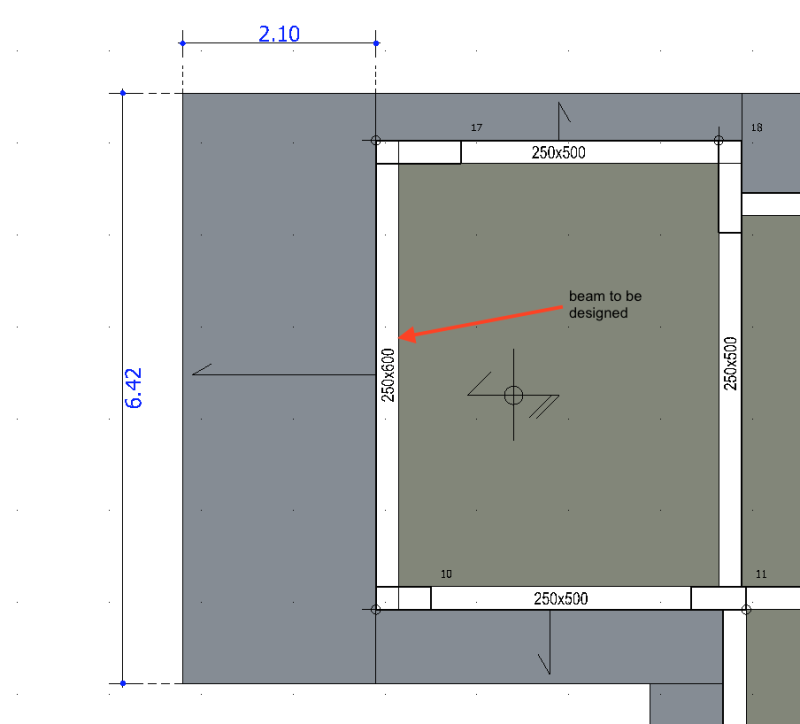
I am trying to design a 2.10m x 6.42m cantilever slab (200mm thick) and the accompanying beam (section: 250x600mm, clear span: 4.60)
that would have to carry the load in order to keep the slab standing.

My initial observation is that its impossible to design the beam reinforcement.
I kept increasing the reinforcement just to observe but it still fails under "Composite Shear-Torsion verification".
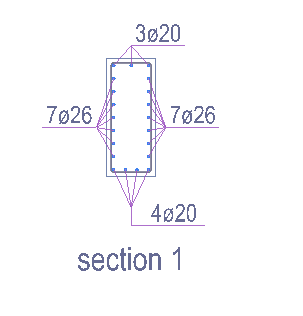
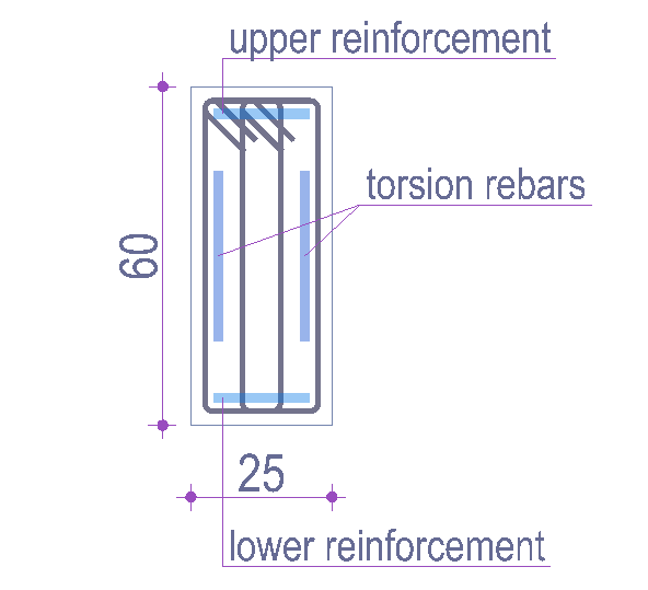
Currently i have 14fi26 for torsion and 7fi20 for bending which is overkill I also have 10mm stirrups with four bars resisting shear.

Screen_Shot_2017-07-01_at_14.13.53_kbvwpw.png


Screen_Shot_2017-07-01_at_14.25.57_jjcfko.png


Screen_Shot_2017-07-01_at_14.26.26_vwu4u1.png


Therefore now i am trying to think of ways to reduce the torsion transferred to the beam by the cantilever slab?

1. My first thought is to use wide shallow beams that extend from the end of the interior slab across the two outer
columns up to the end of the cantilever slab. in this way i can transfer some of the load directly to the columns
and relief some of the load from the beam. (see image below)


2. My next thought is to design the beam as an inverse L-shaped beam therefore adding a a bit more of torsional resistance.
which basically means inserting a shallow beam directly on top of the existing beam which would be embedded within the column
allowing for greater torsional resistance. Again this allows to involve the column more in directly resisting the load from the slab.
(see image below)

3. One more thought is if I am actually modelling this correctly in regards to the torsion transfer from the slab to beam. My question is,
shall i reduce the torsion transfer to the beam or shall i leave it at 100%


What are your thoughts on the above solutions and could you suggest any more solutions to address this issue?

Regards

SUGGESTED DESIGN

Screen_Shot_2017-07-01_at_16.02.36_r1l7u5.png
 
Replies continue below

Recommended for you

OP said:
My question is, shall i reduce the torsion transfer to the beam...

This. In these situation, it is generally expedient to take advantage of the compatibility torsion concept. Google "compatibility torsion concrete" and you'll find ample information, much of it located here. The procedure is as follows:

1) Let the beam crack and shed it's torsional stiffness. Post cracking, the beam's torsional stiffness will drop to 5-10% of it's uncracked value.

2) Run your model assuming zero torsional stiffness in the beam and design the slab accordingly.

3) Provide your beam with a minimum quantity of torsional hoops, as defined by the governing concrete code, to allow the beam to redistribute its torsion and convert it into additional slab flexure.

This a very common procedure in design offices. If you instead try to increase the torsional capacity of the beam, often you'll wind up chasing your tail because that additional strength begets additional stiffness. And additional stiffness begets additional torsion.


I like to debate structural engineering theory -- a lot. If I challenge you on something, know that I'm doing so because I respect your opinion enough to either change it or adopt it.
 
Kellez,

I would agree with KootK and transfer your cantilever hogging moment into the back span rather than trying to get the beam to take this in torsion.
Your 200 thk slab for a 2.1m cantilever look too thin for me.

Regards
 
Hello KootK, first of all thanks a lot for your post that is some great info there, i really appreciate it. Ive done some research and i will do some more later on.

1. Ok so the main thing here is that i will not design the beam for torsion and only provide the minimum torsional reinf. required.
2. Now my question is...since i am not designing for torsion, and i will not provide any resistance to torsion how are the forces redistributed in real life?

Some thoughts:
The torsional moment will now be distributed as a bending moment on the beam
Obviously the columns will experience some bending now in order to hold the cantilever slabs in place (equilibrium)
And finally we have the interior floor slab....is the back span going to provide all the resistance as patswfc suggests?


Hello patswfc well the architect specified it as 200mm but i have not yet designed that, once finished with the beam i will carry on with the slab design.
However do you actually think that its impossible to design such a slab? what ever the steel reinforcement to use?


You can place the concrete with a teaspoon, if you're not careful...

Dik
 
Hi dik,

I didnt quiet get that...do you mean it would be too congested by the bars?
 
You're most welcome.

kellez said:
Now my question is...since i am not designing for torsion, and i will not provide any resistance to torsion how are the forces redistributed in real life?

Who knows? Concrete design mostly follows the logic of what could safely be rather than what will actually come to pass. The compatibility torsion solution that we've been discussing is simply a valid and reasonable equilibrium solution.

Kellez said:
The torsional moment will now be distributed as a bending moment on the beam

Nope. No extra bending moment on the beam.

Kellez said:
Obviously the columns will experience some bending now in order to hold the cantilever slabs in place (equilibrium)

I see no need for the column bending moments to increase. In fact,they may decrease as the torsion that used to be in the beam needed to be delivered to the columns as moment.

kellez said:
And finally we have the interior floor slab....is the back span going to provide all the resistance as patswfc suggests?

Yes. At least that is the story that we're telling here.

I like to debate structural engineering theory -- a lot. If I challenge you on something, know that I'm doing so because I respect your opinion enough to either change it or adopt it.
 
Kellez

1 the torsion results in moments into the columns. if there was no restraint to the beam rotation, there would be no torsion in the beam. The columns provide that torsional rotation restraint.

2 If there is no torsion, the cantilever deflects further as part of the rotational restraint at its support disappears.

You cannot assume compatibility torsion and ignore it without considering the effects of no torsional restraint on the remainder of the system.

Size the beam to be able to take carry the torsion and design it like it wants to act!
 
OP... might get that way, your beams are pretty narrow and if you consider anything but a relaxed torsion, you might have too much steel.

Dik
 
Thank you everyone for your time.

Therefore the final design considerations are:

1. Use the compatibility torsion solution and assume the beam does not resist any torsion
Modify the analysis model to take this into consideration

2. Run the analysis of the new model and design all elements accordingly. The model should effectively distribute the forces accordingly.
I will investigate the results to get a better understanding.


In simple words, do not provide torsional resistance to the beam and design accordingly as KootK said in the first post.
 
Yes, that is one solution. But still provide minimum torsion reinforcement in the beam if you follow that logic!

It all gets down to the definition of "compatibility" torsion. It is a very vague concept. It is a bit like designers ignoring column stiffness for slab/beam analysis. The stiffness affects the results until there is no stiffness. And the only way to have no stiffness is to form a zero capacity plastic hinge in the column. Just about impossible and I do not think it is a good idea. You will always have at least the cracked stiffness, which for a column is probably somewhere between 70 - 100% of the actual stiffness depending on the reinforcing arrangement and the column loading once you consider the effects of axial loading and tension stiffening.

Same thing for your beams rotational stiffness. It can never be 0 in practice.
 
1. Use the compatibility torsion solution and assume the beam does not resist any torsion
Modify the analysis model to take this into consideration.

IIRC, if you use the compatibility torsion solution, you still have to be sure the beam can resist a certain level of torsion (provided for by ACI 318-11, Section 11.5.2). It's been my experience with this equation that the level of torsion this yields is typically higher than what the design torque would be anyway. However, in your case, with a cantilever slab, it might be less. Just something you have to run.

If you do have to estimate the torsional stiffness of the girder (i.e. the compatibility solution doesn't work)......a good means of estimating that stiffness is in 'Analysis of Structural Systems for Torsion' (ACI SP-35). In particular, see the chapter on post-cracking stiffness, p.410 (for a example of it's calculation), and p.425 for a chart showing the ratio of cracked torsional stiffness to non-cracked (for various) parameters of reinforced concrete. (In general, the GKcracked/GKg ratio is equal to about 0.05 to 0.2 in my experience.)

Just a general comment on your design: I've never had a 6' cantilever slab be an issue for just personnel traffic....if there is a problem, you may want to make your beams deeper. (Not sure what the dimension actually are: I see one plan view that shows 500-600 mm and a cross section that shows "60".)


Hello WARose,

Thanks a lot for the resources i will make sure i go through that. I am designing according to Eurocodes and i dont think i have seen any chapter regarding this type of design, but i will make sure i check on the ACI standards. Is there any good design guide (text book) to accompany the ACI standards that could be of any help?


"If you do have to estimate the torsional stiffness of the girder (i.e. the compatibility solution doesn't work)."

Which are reasons that the torsional compatibility may not work?


Regarding the cantilever slab design i will get on to that later.


Is there any good design guide (text book) to accompany the ACI standards that could be of any help?

I think PCA still puts out their "Notes on ACI 318". They typically have put out one for each edition of ACI 318......and it's got a lot of worked examples and is very useful.

Which are reasons that the torsional compatibility may not work?

If redistribution is not possible (see section 11.5.2 of ACI 318), and/or if the compatibility torque [from Section 11.5.2] is greater than what a analysis shows the torque would be (based on stiffness estimates of the supporting members). With regards to the latter, that is what I was referring to before when I said: "It's been my experience with this equation that the level of torsion this yields is typically higher than what the design torque would be anyway."


Status
Not open for further replies.

Part and Inventory Search

Sponsor