Eng-Tips is the largest engineering community on the Internet

Intelligent Work Forums for Engineering Professionals

3 Ball Kinematic DWG Definition

Status
Not open for further replies.

SSO Contractor

Mechanical
Mar 28, 2024
10
0
0
US
Hi,

I'm defining a classic 3 ball, 3 radial v-groove kinematics mount and thinking of treating the 3 radial v-grooves similar to datum targets (spheres instead of circular areas) and in doing so this will lock all 6 degrees of freedom. 3X datum feature "A" of these radial spheres should be all I need to define the rest of the features once I establish 3 mutually perpendicular planes relative to them (shown in red). First time trying this and wondering what other think. Thanks:
 
 https://files.engineering.com/getfile.aspx?folder=e74e58f9-136e-4940-b557-b12345727799&file=No_Tech_Data_-_3_Ball_Kinematic_DWG_Definition.PNG
Replies continue below

Recommended for you

The idea looks fine.
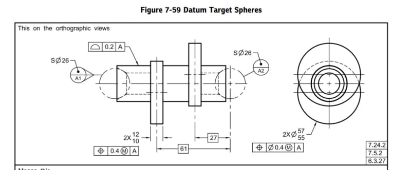
But you can actually use datum targets instead of doing it "similar to datum targets":

Screenshot_20240329_093158_Drive_uuup2t.jpg
 
Burunduk, thank you for pointing that out, maybe it does make sense to just apply spherical datum targets, removing the Position FCF, and leaving it up to Gauge Maker tolerances. I have the feel the Checkers here will have an issue with that, but if it's a sound callout, I'm okay trying to push it through anyway.

The other part that is interesting using spherical datum targets in plane, and radially 120 degree from each other is the fact that, that is all the datum features you need. I can't see better way to callout my datum features being that these 3 v-groove is the only thing that interfaces with the mating part and it does control all 6 degrees of freedom. You can measure axially i.e., the 27 and 61 Basic dimensions shown in your image, but you also create a center point between all the spheres.
 
You would still need to tolerance the v-grooves (qualify the datum feature). The simulator for the datum target spheres would be made to gage makers tolerance, but not the actual v-grooves. It is needed to profile them as a group. BTW, what features are controlled relative to A?
 
It's a metallic, pedestal mirror, and the 3D image I provided is not the same part (just a common example grabbed from the web).

I am defining the v-grooves with a Basic angle, and the v-grooves are tangent with the toleranced spheres on both sides.
 
The spheres you are showing in phantom lines are part of a fixture. Why do you apply size and position toleances to them?
Are you tolerancing the product and its inspection equipment at the same time?
 
So, this is part of the reason I made this inquiry, and why I was tolerancing this 'similar' to datum targets, which is because I know the tolerances of the spherical components that interface these v-grooves and I was trying to incorporate those. I know Datum Targets fall under gauged maker tolerances (10x-to-20x tighter than part tolerances) and for practical discussion, are typically (or maybe always which is what I'm chgallenging) considered perfectly located and formed, but I also see this as working the same way - by tolerancing the 'Size' of the spherical references. It is tangent and in contact with the v-groove on both sides and one could define a v-groove this way. But this is the point of the thread and it's good get this reaction. I will most likely go through the same thing with my Checkers and to avoid/reduce that back and forth, I think sticking to a traditional Datum Target approach is best (even though I may have some convincing to do that Datum A is all that is needed). So, based on this discussion (because everything you've said does make sense to me), I'll make the spherical references datum targets - no Positional and Size tolerances e.g., representing 'actual' counterpart tolerance, and then I'll simply tolerance the v-groove directly, probably using Profile of a Surface w.r.t. Datum A. That should be fine. Thanks again for you responses, good sanity check.
 
What is generally required, and (I suspect) rarely specified for precision mounts such as this, is that all related features need to be within some range for all possible mating feature variations.

It's not a good idea for acceptance to be made with one fixture if an unacceptable result might occur with another, though it is usually done that way because it is most convenient for the inspection department.

There certainly isn't much value in controlling the whole of the groove surface(s) when the mating features only contact a tiny fraction.
 
3DDave, that's a fair point about the spherical contacts on the v-grooves. In reality, there will only be a single contact point on each surface of the 2 surface v-grooves (3x v-grooves and a total of 6 contact points).
 
It's quite simple. The part in question does not have any spherical features. Only the mating part does. Then, you shouldn't be tolerancing any spheres as part of defining this part. You should use datum target spheres and define them by only basic dimensions. The spheres that will be used for inspection, either physical or virtual, are "datum feature simulators", and they will provide the "construction geometry" (datum) for establishing the 3-plane datum reference frame. As such, they need to be as accurate as possible, so that:
1. They are reliable at establishing the datum reference frame.
2. They mimic the average mating part appropriately.
This is why they need to be controlled by tolerances considerably tighter than the spheres on the mating part. It is not up to you to assign those tolerances unless you also design the fixture, in which case you'll be doing it on a separate drawing.

I would not tolerance the datum feature A v-grooves with reference to datum A. Although it may be workable, I would prefer to profile them as a group of "6X" (6 surfaces forming 3 pairs) without datum references and label them as datum feature A by the datum target symbols.
 
Status
Not open for further replies.
Back
Top