Continue to Site

Eng-Tips is the largest engineering community on the Internet

Intelligent Work Forums for Engineering Professionals

  • Congratulations waross on being selected by the Eng-Tips community for having the most helpful posts in the forums last week. Way to Go!

3 different points on pump curve...not adding up? 1

Status
Not open for further replies.

Engineering1012

Chemical
Apr 18, 2016
29
Hello,

I have 3 vertical sump pumps at our plant. I've been having trouble finding where it runs on its curve and need some advice. I took amp readings (converted to bhp), NEW gauge dP readings, and downstream flow meter readings, and none of the points really line up on my curve. Any hunches on what this could be? Air entrapment/vortexing? Dirty suction?...etc? Any advice or tips would be great for a young reliability engineer. I can provide more information if needed.

Thanks!

Frank
 
Replies continue below

Recommended for you

What are you using as a guess for efficiency? How are you getting do readings. The pump curve and your data would be good to see plus sketch of the system and where your readings are taken from

Remember - More details = better answers
Also: If you get a response it's polite to respond to it.
 
Well I did install the re-circulation line as referring to those old posts. I wasn't entirely sure the project needed to be brought up, it was more of a fundamental question in my eyes. The amp is reading was taken by my tech, and I used the efficiency on the motor name plate for calculation. The discharge gauge is taken directly after the piping comes out of the sump, I have accounted for the level in the tank. See the links that Latexman posted. The flow meter comes from a mag meter just downstream of the discharges. This has been inspected and cleaned as well...
 
Why don't you post the data so that it can be reviewed.

Note that the pump has an efficiency separate from the motor efficiency.

What accuracy are you expecting? How close is it to the curve? 1%, 2%, 50%? How big of a pump are you talking about?
 
are the pumps piped in parallel? from a common point on discharge & suction pipes, the piping to/from the pumps may impact operating points if there is not equal resistance. a layout sketch will also be helpful.
 
Agreed, if you dont have sufficent submergence of the pump's feed entrance, air could vortex into the pump. FT readings would be in error, and so would dp developed by the pump. Have you checked that all data points recorded meet this minimum submergence?
 
amp is reading was taken by my tech

After several embarrassing incidents, I made it a policy to only trust data that I personally measure, or observe _very_ closely.


Mike Halloran
Pembroke Pines, FL, USA
 
As with any "pump" problem, usually not a pump problem at all- you need to give us the detail not ask is it air entrainment, vortex, blocked inlet- how are we to know what the problem is, crystal ball gazing is not our fortè.
Check the inlet strainers, check for vortexing / pre- rotation at the inlet, air entrainment, carefully measure flow / head / power with 1 pump operating then 2 and then 3 - report or better still plot 3 curves, advise all relative levels, sketch the layout, supply the original data info for the installation. From this data there is a chance we can see the problem, maybe request some meaningful extra data to make understandable recommendations.

It is a capital mistake to theorise before one has data. Insensibly one begins to twist facts to suit theories, instead of theories to suit facts. (Sherlock Holmes - A Scandal in Bohemia.)
 
In terms of data, the three readings I gathered were 20 psig (at discharge gauge), 25.5 amps, ~275 GPM. Motor is 40 hp, 86% PF, 94.5% efficiency which equates to about 23 hp using 480 volts.

Suction screens were relatively clean, however there is a chance the pumping chamber has a layer of mud on the bottom that isn't necessarily sticking to the screens yet still causing suction issues at the bottom. I am working to get a vacuum truck in here to pump out the chamber.

Here is the pump curve

Pump_Curve_rnhrzj.png


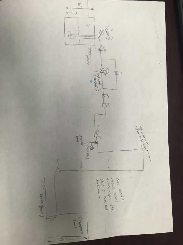
Here is the piping layout. Disregard the flow and pressure readings here... Note there are actually 3 pumps that feed into one common header right when they come out of the sump. One is the primary, second kicks on during high level (>60%, maintains 30%), and third is a inline spare.

Layout_mtov5y.jpg
 
you show 2 different levels for "ground" why are you pumping down hill? what is the relative height difference between sump water level and the final discharge point. Has anyone bothered to calculate the friction loss thru' the pipework? Plenty of people here to assist, but we won't do your job for you.

It is a capital mistake to theorise before one has data. Insensibly one begins to twist facts to suit theories, instead of theories to suit facts. (Sherlock Holmes - A Scandal in Bohemia.)
 
I've analyzed the entire piping system the system is way more complex than what I have illustrated, but that is the general idea. I am not asking anyone to do the job for me, I have calculated my head loss/requirements in the system. I was just asking about possible reasons that I could be getting 3 different data points on my curve from different indicator points.

Ideas like are mag flow meters good indicators if air is present in the line? Or other debris?
Vortexing possibly causing issues.
How accurate are typical motor readings?...etc.

Just was interested in any ideas or experiences people have came across to attack the problem efficiently.
 
Ok, Now you've given us some data.

Some basics.
I can only assume that you have the right pump curve for the pump you're looking at. Is it the 9.5" curve we're looking at
Questions - You said in an earlier post " I did install the re-circulation line as referring to those old posts. " Where is it on your sketch? How much flow is going through it.

Is this the test curve for that pump or a "generic" one? They can be 10-15% different from reality.

The immeadiate thoughts I have are:
Based on your sketch and reading of 20psi, the differential head across your pump appears to be about 55 ft. The intersect with your curve would then give a flow reading of about 1500GPM and a shaft power requirement of about 27 hp. So something a bit odd there alright - i.e. where is that flow going?

If your flow rate is correct (275gpm) and you're operating on the far left of the curve then differential head and pressure at your guage position should be much higher.

So maybe your inlet is clogged, the impellor coated in mud, something wedged in the discharge, you impellor is eaten away or your readings are not where you think they are. Possibly rotation (has anyone checked?), voltage at the motor is higher than 480V?, shaft or bearings not lubricated?

Anything more you can give us?


Remember - More details = better answers
Also: If you get a response it's polite to respond to it.
 
Yep, 275 gpm < the pumps minimum required flow.

Good luck,
Latexman

To a ChE, the glass is always full - 1/2 air and 1/2 water.
 
There is a semi-open impeller.

All of these data points were taken with re-circulation line closed. The whole reason for the initial re-circulation line was a quick and cheap way to protect the pumps before we can get another project for VFDs implemented (already have done analysis on this capability). It was believed that the fundamental issue with these pumps are that during 95% operation they operate around 300 GPM which is basically at min flow. But now I am starting to second guess the readings from the flow meter. Interestingly, the pump seems to be happy when the discharge gauge reads about 20 psig.

I had a 3" recirculation line put in, but just have the valve slightly opened now. Opening it too much cavitates the pump and the discharge gauge drops to about 11 psig ish (which makes sense on the curve). We tried to get exact flow reading but due to air in the line.

Bearings/shaft are lubricated and voltage is definitely 480, rotation has been confirmed as well. If something was wedged in the discharge wouldn't that create a higher pressure on the gauge due to back pressure?

Thanks again everyone.
 
So where is the air coming from?? Sounds like at low level and low flow you're vortexing afoot into the inlet. I don't think you have all your impellor there. Suggest you pull the pump out and see what it looks like.

Remember - More details = better answers
Also: If you get a response it's polite to respond to it.
 
Not totally sure, we operate at 35% level which I believe should be adequate submergence. I hear you on the impeller however we did have a brand new pump swapped in there and it exhibited same exact characteristics...
 
What does 35% mean in distance. Can you see inside aump during operation?

What does this pump inlet actually look like? If the bottom of the sump is full of crud then your pump might be inside a sump of mud causing friction losses or more vortexing than you would normally expect.

Remember - More details = better answers
Also: If you get a response it's polite to respond to it.
 
About 3.5 ft level sorry about that. And you can't really see inside the bottom of the sump, and unfortunately this sump can't ever be stopped. I'm working on a PM to get vacuum truck periodically to pump out the pumping chamber. We already have one that comes out to pump out the settling chamber.
 
Status
Not open for further replies.

Part and Inventory Search

Sponsor