Eng-Tips is the largest engineering community on the Internet

Intelligent Work Forums for Engineering Professionals

  • Congratulations waross on being selected by the Tek-Tips community for having the most helpful posts in the forums last week. Way to Go!

3 ph to 1 ph VFD for a low PF inductive load 4

Status
Not open for further replies.

edison123

Electrical
Oct 23, 2002
4,409
0
0
IN
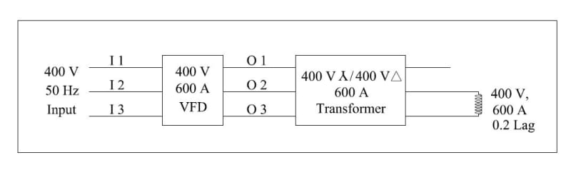
I have requirement of variable voltage, variable frequency (45 to 65 Hz) single phase testing application where is the load is mostly inductive (0.2 lag typically) and have in mind a 3-phase to 1-phase VFD.

If the 3 phase input is 400 V, 50 Hz, what will be the maximum 1 phase output voltage?

Will the 3 phase input currents be balanced for 1 phase output current?

Since the 1 ph output load is inductive with low PF, will the VFD 3 ph input PF be inductive or close to 1 ?

The 1 ph output current maximum will be 600 Amps. Do 3 to 1 ph VFD's exist in that current rating?

Muthu
 
Replies continue below

Recommended for you

The rectifier on the input of the VFD simply passes current from the highest phase voltage. The input side won't see the single phase output. There will not be balance issues.

The maximum bus voltage will be 560v. The maximum output voltage will depend on load.

600 amps is an expensive drive. I wonder if a 3 phase unit could be programmed to fire the gates in parallel so that you would only need to use a 200 amp rated drive?
 
Thank you, tugboateng.

What would be the PF on the input side?

How much output voltage will change with the load?

I am also looking at a Scott connection 3-ph to 1-ph transformer, where I am given to understand the primary current distribution will be 30-30-40%. I would have to put in PF correction caps to reduce that input current. And the frequency cannot be changed, which I can live with.

If the VFD will correct the input PF to about 1, then I can do cost comparison with Scott trafo+PF caps. The whole idea is to reduce the input current.

Muthu
 
You can not ask what the power factor into a VFD is without defining which one.

Don't forget the power factor is two things. Lead-lag and distortion. The standard lead-lag into a drive is about pf=1.
The distortion power factor can be considerable!

Most VFDs the size you're talking about would freak-out into a single phase load.
Remember also that the output of a VFD is a highly complex PWM signal that looks sort-of like a sinewave because of the inductive aspects of a 3-phase motor. Will this single phase load swallow this?

You might be better served by feeding a transformer with the drive and using only two of the phases out of the transformer.

Keith Cress
kcress -
 
Thanks, Keith.

I should have stressed more on the reduced input current than the unity PF.

If I feed a Wye/Delta transformer via VFD, use only two phases on the Delta side for the inductive load, will the input currents to the VFD be balanced on all three phases and more importantly, will they be low?

Muthu
 
Many VFD do not allow 2 phase operation (1 phase unconnected)... most VFD enter in error when one motor phase is lost.
Even that some allow (or can choose by parameters to ignore on phase lost), for such current - 600A, may arise other problems.
If input voltage is 3x400V, maximum output is 3x400V, so 400V line to line (between 2 phases).
If you need constant voltage in 45-65Hz range need to programm VFD with base frequency at 45Hz.
Need to check if load allow square wave voltage or close to sinus only (need an output VFD filter), peak voltage tolerated and dv/dt.
If variable freq is not mandatory I think is cheaper and safe is to use a transformer solution.
I tested VFDs with single phase motors but at low power... below 1kW.
 
What voltage do you need? You've only mentioned amperage so far. Based on your description this will perfectly meet your requirements:


For probably 1/4 the cost of an industrial VFD with that rating.

Multi-process welders have both variable current and variable voltage modes controlled with potentiometers. This would be very simple to integrate a remote control to integrate in to your process.

Expect peak output voltage to be around 80V.
 
Most VFDs have an input rectifier (there are some models that have DC input only, most of them in multi-axis systems).
After rectifier there is a DC bus capacitors bank that feed then 3 phase inverter.
If one phase of inverter remain unconnected and load is inductive type there is no problems with VFD input current balance.
For high inductive load and at such current will be a problem with disconnecting load (high voltage spike)... will be better to reduce voltage from VFD control and then switch off load.
 
The schematic for the proposed system below.

What will be the I1, I2 & I3 and O1, O2 & O3 currents for a single phase 400 V, 600 A, 0.2 PF inductive load on transformer secondary?

400_V_600_A_VFD_Line_Diagram_avu8eq.jpg


Muthu
 
I'm doubtful that will work, but a VFD is a power conversion device so input currents are always typical of a 6-pulse rectifier with levels matching that required to feed the real power used by the load.
 
The basic issue ist that a in a single phase load the power fluctuates with 2 x line frequeny while for a symmetrical 3-phase system the power is constant over frequency.

transformer connections can't adress these issue. A Scott transformer can connect connect two identical single-phase loads to a three-phase systemto appear symmetrical, but not a single one. This is the basic challenge of induction heating equipment.

Solutions are:

- Steinmetz circuit(rarely used today due to complex swichgear)
- Inverters with a large energy storage in the DC-link (either an DC-link inductor or a DC-link capacitor)

My former employer manufactures inverters with a suitable topologie for induction heating, but they rarely do inverters at such low power (48 kW). That was the size of our scaled down model to test our controls 20 years ago.
 
Today, I did the inductive load test via a 600 Amps Variac connected to a 400 V, 500 KVA, 695 Amps DG set with the inductive load connected across the two phases of Variac for over an hour.

Inductive load was 345 V, 525 A with 0.3 pf and the measured KW was 54 KW.

Generator current across the two phases was 480 Amps and thankfully it did not kill the machine.

Soon, I plan to repeat the test with a Scott connection trafo with PF correction capacitors on the trafo primary since the VFD method seems complicated and costly.

Thank you all for your time and tips.

electricuwe

This is not a single phase per se. I am just using two phases and the frequency is 50 Hz.

Muthu
 
Sorry, just recogized that my previous post should read "..constant over time".

edison123, for the power issue it does not matter if a single phase load is connected phase to neutral or phase to phase.

In your case the compensation for sure will help to reduce currents, but don't expect a further improvement by using the Scott-transformer.
 
Status
Not open for further replies.
Back
Top