sysengineer
Electrical
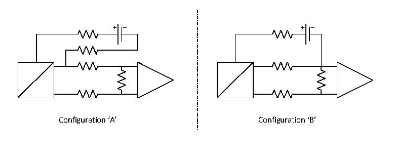
Just wondered if anyone can offer some analysis on the following configurations for a 3-wire transmitter circuit? I have recently been presented with an unfamiliar configuration whereby the sensor 0V is distributed back on two leads resulting in a pseudo 3 wire arrangement using 4 lead wires in total (see Figure 1).
In my previous experience with 3 wire configurations the 0V terminal has one connection. I'm attributing this to bad design as my gut feeling is there is something wrong with this circuit but I can't explain why. I'm thinking there could be issues with potential differences in signal ground but I'm stuck.
Can anyone offer some analysis?