R1chJC
Marine/Ocean
- Apr 15, 2015
- 51
I'm creating a 3D model of an external involute spline in SolidWorks.
The model is to be used directly for manufacturing programming, as such the model needs to reflect as best possible the required geometry at mid tolerance.
I've created the involute flanks with parametric equation curves and produced the minor/major diameters etc.
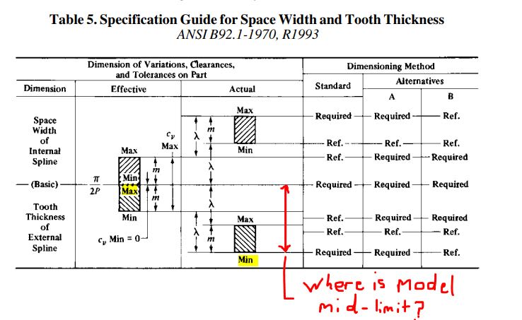
However, I'm struggling to decide what the tooth thickness should be. The manufacturer would like the teeth at mid-tolerance. Does this mean I should model mid-effective or mid-actual tooth thickness, or something else? Not sure how I accommodate for process variation either. See attached.
Spline standard is Flat Root, Major Diamaeter Fit ANSI B92.1 1996.
Any help would be appreciated.

