Continue to Site

Eng-Tips is the largest engineering community on the Internet

Intelligent Work Forums for Engineering Professionals

  • Congratulations KootK on being selected by the Eng-Tips community for having the most helpful posts in the forums last week. Way to Go!

4-20 mA analogue signal conversion

Status
Not open for further replies.

vlc

Student
May 7, 2021
3
Hi, I have the following control setup:
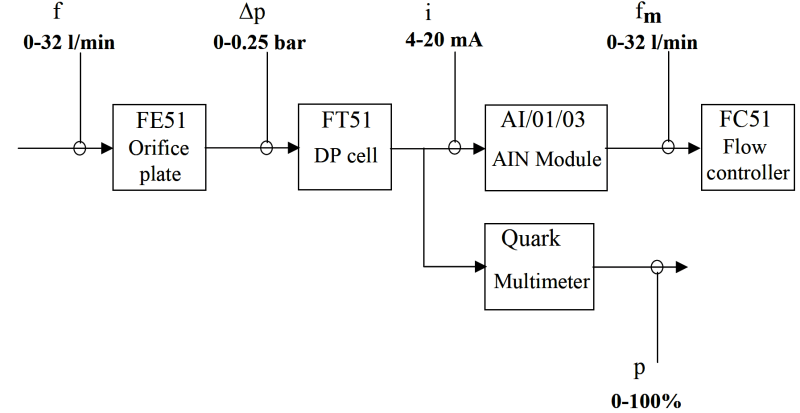
Control_diagram_f0inxd.png

For that, I have data recorded for every I/O block, and I am asked to determine the function used by the AIN block to convert from an analogue 4-20 mA signal to a flow value in the range of 0/32 L/m. The plotted data looks like this:
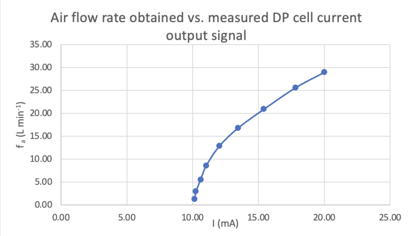
f_vs_I_vipj9e.png

How would you obtain that function?
Thanks for your time
 
Replies continue below

Recommended for you

Start by plotting on logarithmic scales and find the slope of the best fit line, then pursue manual fitting, looking to minimize the errors between data points and your function.
Google "least squares curve fitting"
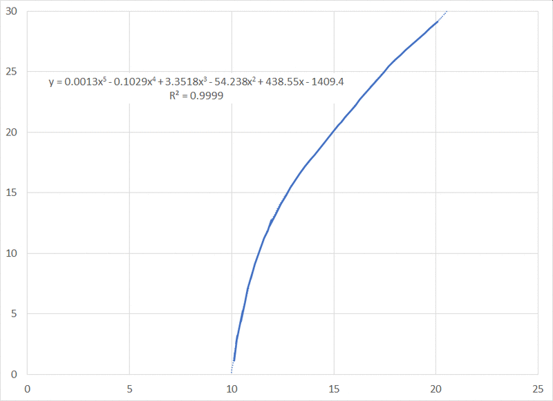
Or try various functions using the curve fitting routines in Excel.
 
If you offset your 4-20 mA signal by -4mA, and work with a 0-16 mA signal the curve should be a square function of the flow.
I haven't worked much on process controls for many years but back in the day of pneumatic instrumentation and 3-15 PSI air signals, we used a component called a square root extractor ahead the DP transmitter.

Have you check the instrument calibrations?
A properly calibrated instrument should output 4 mA with zero air flow.

If you are working in a lab, that DP cell may last been used for an application with an elevated or depressed zero.

Bill
--------------------
Ohm's law
Not just a good idea;
It's the LAW!
 
Here is one process:
image_mdsvny.png


Bill
--------------------
Ohm's law
Not just a good idea;
It's the LAW!
 
Status
Not open for further replies.

Part and Inventory Search

Sponsor