Eng-Tips is the largest engineering community on the Internet

Intelligent Work Forums for Engineering Professionals

  • Congratulations waross on being selected by the Eng-Tips community for having the most helpful posts in the forums last week. Way to Go!

4 Bar Linkage Tolerance on Lengths 1

Status
Not open for further replies.

Mandrill22

Mechanical
Jul 30, 2010
113
US
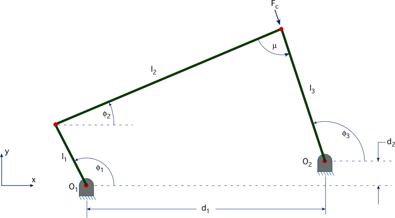
I have a bar linkage system that ends up being a sort of 4 bar linkage. There are 2 bars running in parallel on either side of the "joints".

Each joint has a shaft with a bushing, with an H7/h7 fit.

My question is if there is an equation to determine what the tolerance would need to be from hole-to-hole on each bar.

Images attached.
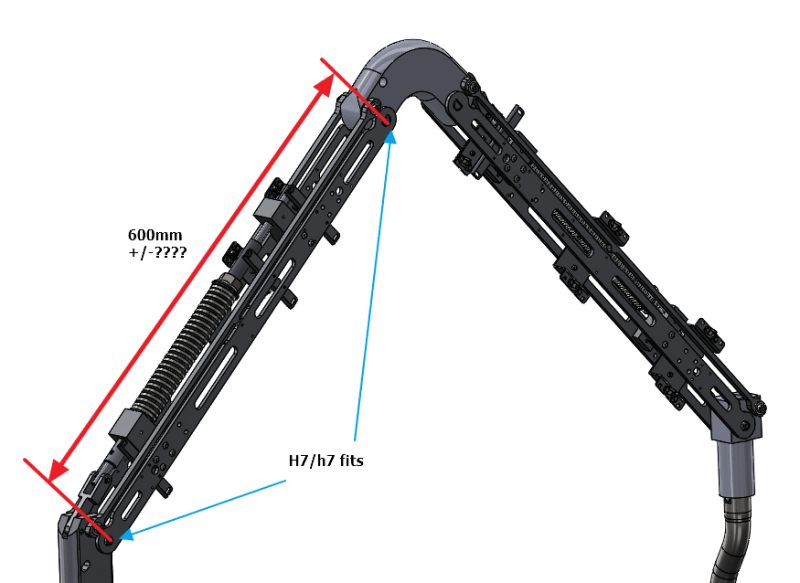
bar_fits_rsfher.png

FBLDescFig1_x3zzxl.png
 
Replies continue below

Recommended for you

I think that would depend very much on the application. A car suspension and pick place robot could both have 4 bars and different precision needs. I think if you look at your everyday shop tolerances and see if your worse case is acceptable for the application. Using CAD, it's not too hard to simulate the inversions of the mechanism and see what effect changes in length would have on your output position or intended motion.

TL;DR- Move it around in CAD, it does the math for you.
 
If I'm understanding your mechanism, you have a round rod and a flat link right next to each other? And the distance between them is I[sub]1[/sub]? Looks like a difference in the 600 mm hole location for those 2 pieces would make it tough to assembly to the elbow at the top.

 
wouldn't a tool fixture help to align pieces before you drill ?


another day in paradise, or is paradise one day closer ?
 
As moon161 said, very much application dependent.

If this holds a desk lamp then you don't really care if the joints are slightly twisted or the end of the arm ends up in a different place for a given spring force or initial setting.

If this is part of an actuated assembly where positioning of whatever is on the end of the arm is critical, I would recommend making the tolerances easily achievable for your manufacturing method and then creating teaching fixtures to create you home/offsets for each assembly.
 
It seems to me that the issue is more of concentricity of the bar holes between the two sides of the shafts; if the two upper bars differ by more than the tolerance of the hole/shaft, then the shaft will be cocked and the arm might bind.

TTFN (ta ta for now)
I can do absolutely anything. I'm an expert! faq731-376 forum1529 Entire Forum list
 
Right, Concentricity is the key. That's what I'm wondering. There are steel backed PTFE bushings that would compress.There a few problems with that:

The load on one compression member will be higher than the other. Same goes for the tension member (SF already 4 at nominal)
There will be a compressive load on one member and tension on the other. The resultant rotational resistance would be small, but would still throw things off.
The maximum compression before failure of the bushing is 0.27mm, so even if the bushing absorbed all of the additional force, it’s not going to withstand the misalignment.
The bushing life would drastically decrease with the additional normal force.
 
RB1957 is close on target.
matching 2 details is difficult but doable.
matching 3 details in line is even more difficult.
the true position would have to be very tight.

suggestions, key is mfg method.

there is many ways to try solve this issue.
not knowing the type & hardness of the part material it is a guess.

preferred method (old school) is to design and build a drill jig to machine the holes.
the holes for the bushing would be jig bore and/or jig ground.
holding the true position of the holes exact. allowance for wear.
cost of the fixture can be amortized into a large production run.
would pay for it self in one lot

tighten the requirements to .001 true position. which is very tight, and expensive for production.
good for short run, R & D, proof out design

match drill and ream all 3 details concurrently. all there details will have exact inline position.
but not preferred for precision moving parts, could be slightly out of alignment position.
difficult to do, only as a last resort.


Status
Not open for further replies.

Part and Inventory Search

Sponsor

Back
Top