Continue to Site

Eng-Tips is the largest engineering community on the Internet

Intelligent Work Forums for Engineering Professionals

  • Congratulations pierreick on being selected by the Eng-Tips community for having the most helpful posts in the forums last week. Way to Go!

4-Sided Open Face Wood Frame Diaphgram - Wind Design 1

Status
Not open for further replies.

mtuhusky

Structural
Jun 18, 2011
13
I am working on a project that is a 3 story wood framed multi-family building. The architect wants to use Zip-R sheathing on the exterior with no wood structural panels directly attached to the studs. If you're not familiar with the product it is 7/16 wood structural panel with rigid insulation pre-attached (in my case 2"). This product has some shear capacity but it is limited. Aside from the crappy shear capacity I have other reservations about sheathing the building with only Zip-R with no WSPs directly attached to the wall studs. I would prefer to create a sandwich with sheathing attached to the studs and Zip-R attached to that. Nevertheless I'd like to explore the idea of not relying on WSPs or Zip-R for shearwalls on the exterior.

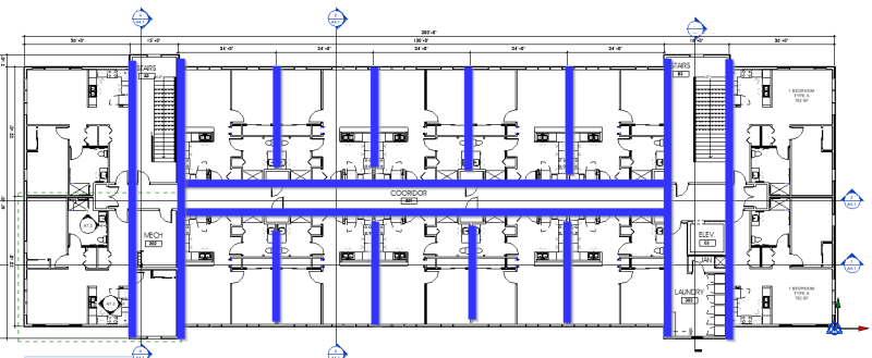
I'm in a very low seismic region so wind design always controls our structure's lateral design. I'm thinking about designing the building as an open faced structure on 4-sides. In this condition there would be no sheathing directly attached to the exterior walls and the Zip-R would would not be structural. 1) What are you're thoughts on distributing the wind load to the shear walls using a rigid diaphragm? 2) If I make the assumption that the diaphragm is rigid, how do I ensure that it is indeed a rigid diaphragm? I am familiar with the procedure for seismic design but it seems like that procedure doesn't directly translate for wind load design. I've attached a image of the floor plan with my proposed shear walls in blue.
 
 https://files.engineering.com/getfile.aspx?folder=45235504-cc3a-4818-be05-60a688c8b482&file=Rigid_Diaphragm_Plan.png
Replies continue below

Recommended for you

My concerns are around the exterior wall on the L/R sides, and that section with the stairway. You have a very unique diaphragm aspect ratio in the stairway/mechanical area, how would you justify anything in that section? What happens when the forces from wind are in the L/R direction? You have 26ft to the wall line, what happens when wind blows N/S, what's your diaphragm deflection?

I would argue that you cannot ignore the contribution of the zip sheathing, unless it's something like an order of magnitude less stiff than the WSP shear walls you are designing. Does the zip system consist of hold downs to provide any overturning capacity?

I've always taken the approach of assuming a wood diaphragm as semi-rigid, I've never really bought into the whole flexible diaphragm approach. I think you can model as semi-rigid and determine your demands based on that technique.

Here is another thread that discussed a similar situation, although at a smaller scale: Link
 
Image inline:
Rigid_Diaphragm_Plan_awfbmd.png
 
Well I'm going to divert into terminology a moment.

It's not an open building, it's enclosed and you don't like using the exterior walls for shear, they have some shear capacity you are ignoring and that's fine (it should be stable if you design correctly and ignore their strength, like many engineers do (I presume) in neglecting gypsum board strength in wind design when the exterior is a WSP (plywood or OSB).

To design it this way you need to prove the diaphragm is rigid via calculation, (maybe) using established principles of mechanics. There are ways to do this.

In the simplistic sense, regardless of the strength of the diaphragm, if you don't allow the exterior wall to resist the wind shear (along their length), the load has no other choice but either "magic load transfer" or by ending up in the interior shear walls, if the diaphragm has sufficient strength for the load, it can transfer the load regardless of relative stiffness, and the corridor walls are likely equally stiff so they attract more or less equal force (51%-49% or whatever minute effects happen, wind eccentricity, the vagaries of construction, a stray piece of blocking that acts as an unintended drag strut), and again, the exterior wall remains somewhat valid for strength as well, so... to me the design is conservative and based on principles of mechanics even if you use tributary area versus a rigid diaphragm analysis I think the results will be very similar.
 
I agree this is an enclosed building for wind design. To clarify my thread title should read "open front" as defined in the SDPWS. The zip system is just a sheathing system. If you use it in shearwall construction you would provide holdowns just as you would for a WSP shearwall. Typically open fronted structures have 3 sides of LFRS, creating a c shape. In this case the ends cantilever without the "c-shape". In the plan I attached when the wind load is up/down on the plan is it possible to construct a wood diaphragm with enough rigidity that can transfer the load at the ends into the interior shearwalls?
 
That end looks functionally unstable as there's just the one wall vertically and you really want that C shape. You could perhaps get diaphragm chords and collectors to cross the stairwell to get your three "walls", but the stairwell has different levels in places (landings) and nothing besides stringers in other places.

Those stairs are in a very odd location. Typically they are the end of the building, as I suspect you know. That's making your approach far more difficult.
 
I generally use 1 1/2" ZIP over 7/16" OSB in the high shear areas when the Arch has specified 2". I hate that crap.
 
I feel like if you put any sheathing under the zip sheathing you might as well do the whole building because otherwise you get a weird bump in the wall section. I've looked into strapping the top and bottom chords of the end diaphragm back through the stairs but then you have the issue of the stairwell interrupting the strap. Also you'd be strapping to the open front of the interior diaphragm which doesn't work either. It just feels like they need to eat the cost of sheathing the building. I swear the architects must own stock in the zip sheathing, they think it's the greatest thing since sliced bread.
 
mtuhusky said:
I feel like if you put any sheathing under the zip sheathing you might as well do the whole building because otherwise you get a weird bump in the wall section.
You use thinner zip at the sheathed areas. (Hence why my post said 1 1/2" versus the 2" you stated)
 
I would use the Zip-R walls as shear walls to the extent they work. If, per your plan, all the blue interior walls will be sheathed with structural panels (not Zip-R), do you really have that much demand on the exterior walls. The short end walls seem like they won't need to resist much considering the stair walls will be shear walls. Maybe the long walls will need segments (middle and end bays perhaps?) where sheathing is attached to the studs with Zip-R over it, as mentioned by XR250. I would do that before trying to justify a rigid diaphragm or whatever.
 
Status
Not open for further replies.

Part and Inventory Search

Sponsor