Eng-Tips is the largest engineering community on the Internet

Intelligent Work Forums for Engineering Professionals

  • Congratulations waross on being selected by the Tek-Tips community for having the most helpful posts in the forums last week. Way to Go!

5 ton forklift on 8" slab 3

Status
Not open for further replies.

CDLD

Structural
May 20, 2020
209
1
18
CA
Good morning,

I am checking a 5-ton forklift on a 8” slab cast on a 3” metal deck (formwork only).

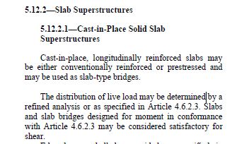
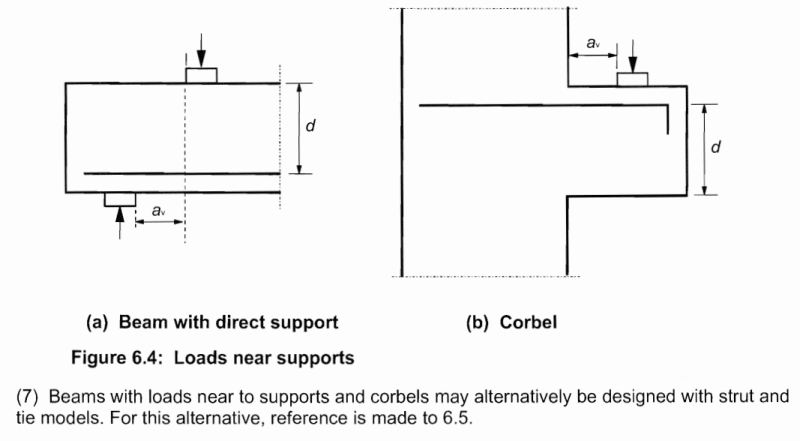
By a strict read of the code (ACI 318-19), concentrated loads located close to the support (<d) have a critical section located at the face of the support for one-way shear.

By locating the front axle directly adjacent to the support (ie. 2” to the center of wheel), I get a very small effective width (using “French distribution method”), which seems overly punishing.

Where should I locate the front axle relative to the support to achieve reasonable results?

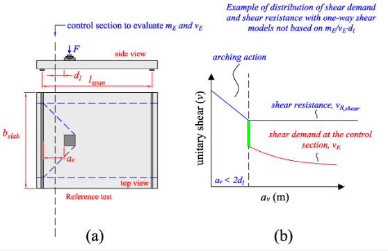
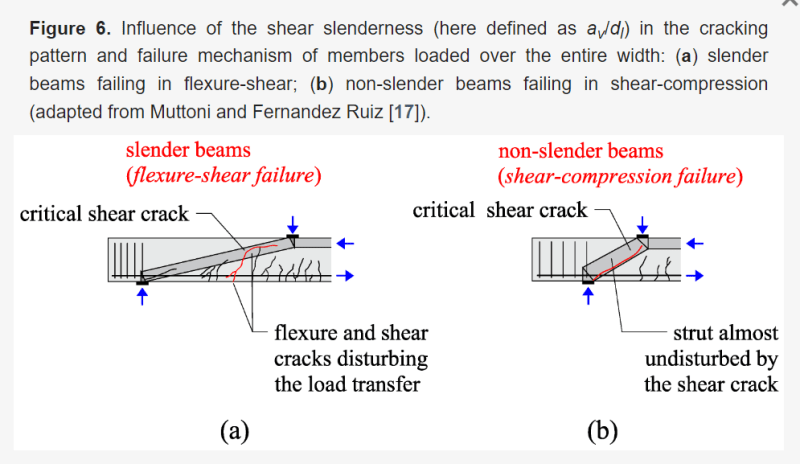
I was reading these articles:Link Link, and it seems that the most critical position occurs when the front axle is clear from the support by 2*d (due to arching), however these articles are tailored to Eurocode and I’m not sure if its appropriate to use with ACI (cl. 7.4.3).

Thank you.
 
 https://files.engineering.com/getfile.aspx?folder=3191eb88-a77c-469f-b4ce-607a16f5fb5c&file=French_load_spreading_method.pdf
Replies continue below

Recommended for you

The steel deck institute has some guidance on this, but you may not like the results. The fact is that the load just can't/doesn't spread out much when you are near the support.

Do you have a 5-ton capacity lift, or 5-ton gross weight, or 5-ton front axle load? It makes a big difference. My gut from having done quite a few of these says "no way" for a 5-ton capacity lift. Loaded front axle loads would be waaay too high. You might be able to get a 5-ton front axle load to work - a 5 kip wheel load seems doable. 5-ton gross loaded vehicle weight would be no problem at all.
 
5 ton rated capacity with a 22kip front axle load.
I am familiar with the SDI methodology, it is slightly more conservative than the French load spreading method. Both methods have very small effective widths when close to the support.

I am really tempted to place the load 2*d clear from the support as mentioned in the linked articles.

Following SDI method with the front axle directly adjacent to the support would require a 17" slab - which is obviously excessive.
 
Our highway bridge decks are similar (steel formwork, 8" concrete deck). Factored design wheel loads are 16 kip * 1.75 = 28 kips = 14 ton. AASHTO doesn't require a check for shear. This includes deck slabs supported by transverse stringers/floor beams. Granted, the supports for our decks are continuous, so if yours is discretely supported, your situation may be more critical.

There's also this from the AASHTO bridge design spec, which may be helpful in determining the distribution width for the loading:

culvertslab1_orys5j.jpg

culvertslab2_r9f66o.jpg


It's for top slabs of culverts, but it would seem to be similar in configuration to your situation.
 
BridgeSmith said:
AASHTO doesn't require a check for shear.
This is surprising to hear; I imagine you are referring to some sort of empirical design with shear checks built in.

BridgeSmith said:
Granted, the supports for our decks are continuous, so if yours is discretely supported, your situation may be more critical.
My situation also has continuous bearing (slab on steel beams).

BridgeSmith said:
There's also this from the AASHTO bridge design spec, which may be helpful in determining the distribution width for the loading:
This yields an 9 ft effective width for an 8 ft clear span. This seems excessive and also taken out of context.
I also imagine your trucks have a larger track width. A 5 ton forklift has a track of about 3.5 ft.
 
Actually 9 ft isn't that excessive. I was thinking of 1 wheel but it is for the entire axle.
Still, I believe the effective width equation from the image you posted would be taken out of context for elevated slabs.
 
I would check two way shear not one way shear. If this wheel load was on a 2' wide beam, would you only consider a couple inches of the beam effective?
 
canwesteng said:
If this wheel load was on a 2' wide beam, would you only consider a couple inches of the beam effective?
No and I wouldn't for a slab either. Current SDI equation has a minimum effective width equal to the load width plus 2 times the depth of slab.
 
This is surprising to hear; I imagine you are referring to some sort of empirical design with shear checks built in.

Actually, no. There are no checks for shear in bridge decks. The empirical deck design specifies the area of reinforcing each way in the top and bottom layers, and that's pretty much it. From the AASHTO LRFD spec commentary:
deckcommentary_tr1rca.jpg
deckcommentary2_rxorbn.jpg


One caveat contained in the next paragragh should be noted: "Although current tests indicated that arching action may exist in the cantilevered overhang of the slab, the available evidence is not sufficient to formulate code provisions for it (Hays et al., 1989).

This yields an 9 ft effective width for an 8 ft clear span. This seems excessive and also taken out of context.
I also imagine your trucks have a larger track width. A 5 ton forklift has a track of about 3.5 ft.
The design truck is assumed to have a 6' spacing between the centers of the wheel loads on an axle. so, to be consistent with the distribution width, the 96" in the equation would be reduced to 66" for your forklift load.

Still, I believe the effective width equation from the image you posted would be taken out of context for elevated slabs.

It's for the top slab of a box culvert, so a slab supported on 2 sides by concrete walls and spanning over the culvert opening in between.
 
The loaded front tires on a 5-ton forktruck may be 50% higher than an H-20 tire load with a contact patch half as large. You also often have a slab on metal deck and not a site-formed full-depth well-reinforced slab. While we probably don't understand the one-way shear distribution when the slab is loaded near the support, I'm not comfortable with the ignoring shear because the bridge guys don't check it.
 
BridgeSmith said:
The design truck is assumed to have a 6' spacing between the centers of the wheel loads on an axle. so, to be consistent with the distribution width, the 96" in the equation would be reduced to 66" for your forklift load.
I stand corrected, this equation is indeed applicable, although I believe the 96" would actually be reduced to 4'-6" (54") since the forklift tires are only about 12" wide and I believe your design truck tires extend 1 ft each side from the center of track.

This would mean for an 8ft span, AASHTO gives us about 5.5 ft of effective width for the axle, which is still far off calculation wise. I have a load of 22*1.6 + deadweight of slab and only a resistance of +- 4kips/ft for an 8" slab. This is about 75% overstressed. What is shocking to me is how the calculations are so far off - 8" slab with a 5 ton forklift is quite standard in the pulp and paper industry. Also, I understand the deck has a fair bit of shear resistance, but this is typically neglected due to corrosion.

Does AASHTO have an equation for the trucks travelling perpendicular to span, this seems to be even more critical?
Screenshot_2023-08-03_091459_tjdnux.png
 
Also Bridgesmith, I appreciate the information you provided on the AASHTO empirical deck design method - this is quite insightful on an area (bridges) I don't have any experience in.
 
JLNJ said:
The loaded front tires on a 5-ton forktruck may be 50% higher than an H-20 tire load with a contact patch half as large.

Bridgesmith mentioned his design wheel loads are 16 kips which is almost 50% higher than the 5-ton forklift wheel loads. Granted forklifts do have a smaller axle.

JLNJ said:
While we probably don't understand the one-way shear distribution when the slab is loaded near the support, I'm not comfortable with the ignoring shear because the bridge guys don't check it.
Agreed, however specifying a 17" slab for a 5-ton forklift also doesn't make any sense.
 
JLNJ said:
The loaded front tires on a 5-ton forktruck may be 50% higher than an H-20 tire load

It appears you may be correct:

CDLD said:
I have a load of 22*1.6 + deadweight

Although, the load factors for the HS-25 design truck we used when we designed under the AASHTO Standard spec, makes the effective load we were designing for 1.3*1.67*20 = 43.42 kips.

JLNJ said:
...with a contact patch half as large.

The tires must run a very high pressure. 22 kips on a 100 sq. in. patch yields a contact pressure of 220 psi, which must be matched by the internal tire pressure.

CDLD said:
8" slab with a 5 ton forklift is quite standard in the pulp and paper industry.
They apparently calculate the shear capacity differently. Might be something to look into

CDLD said:
Does AASHTO have an equation for the trucks traveling perpendicular to span, this seems to be even more critical?

In typical slab-on-beam bridges, the slab spans perpendicular to the direction of traffic. If you meant traffic traveling parallel to the span, then the analogous case would be the top slab of a typical concrete box culvert under less than 2' of fill (including at-grade top slabs) or a slab bridge, for which we have previously discussed the distribution width.

The AASHTO spec has this to say on slab superstructures:
slabsuper_j79ckg.jpg

Here's the section referenced:
slab4623_sfgecy.jpg
 
The SDI equation probably assumes one way load distribution and one way rebar distribution to go along with it. I'm not sure how a one way shear failure can occur on a two way slab
 
BridgeSmith said:
The tires must run a very high pressure. 22 kips on a 100 sq. in. patch yields a contact pressure of 220 psi, which must be matched by the internal tire pressure.
Correct. Although for my case they are cushion tires (Approx. 4"X12" contact).


No matter which method of horizontal load distribution I use (AASHTO, SDI, French Method), the results will show excessive overstress for a 5 ton forklift directly adjacent to the support; which is not consistent with industry standards and leads me to my original question - "Where should I locate the front axle relative to the support for most critical effects on one-way shear".

I'd like to focus on "arching action" and whether its appropriate to use with ACI.

Below is a snippet demonstrating when the load position is < 2*d from the support the shear resistance increases due to arching.
Screenshot_2023-08-03_142552_qobzv8.png


When load is placed near support, concrete strut forms, reducing the shear demand on the section.
Screenshot_2023-08-03_143013_setohk.png

Snapshot from Eurocode, expressing arching action as a reduction factor, beta, applied to the shear demand at the support.
Screenshot_2023-08-03_143317_tjuvfa.png

Screenshot_2023-08-03_143442_nfjuil.png
 
BridgeSmith said:
It can't. On a 2-way slab (or away from the edges of a sufficiently wide one-way slab), the shear failure mode is by punching shear.
canwesteng said:
I'm not sure how a one way shear failure can occur on a two way slab
The slab I have is typically designed as one way as the width to span ratio is sufficiently large.
Anyway, this is a snippet from my previously linked article explaining that the slab could indeed fail in one-way shear.
Screenshot_2023-08-03_145510_mk66ic.png
 
Ah, yes - concentrated loads on slabs, it would be nice if ACI would provide some guidance on this topic which I'm sure many engineers have spent hours banging their head against the nearest solid object.

In my opinion, one way shear on a reduced effective width too close to the support is not a valid failure mode. I view this essentially as a yield line analysis problem and as such there must be some flexural demand to cause this reduced effective section. What I have done in the past is check two-way shear close to the support with a reduced perimeter, check one-way shear based on a load distribution angle from the back side of the contact area (I use 45°) to the support for the effective width, and check flexure with your favorite reduced effective width equation.
 
Status
Not open for further replies.
Back
Top