Oblsss
Electrical
- Nov 7, 2013
- 42
Hello everyone,
I came across the attached specification for MV power cables used in FPSO applications.
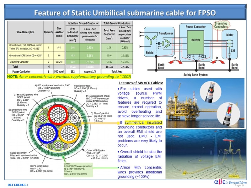
My experience is limited to the onshore industry and I can not find the use of the 6 ground wires located in the interstices between the 3 MV shielded power cores.
A large fault current could have been dealt with the use of large cross-section metallic shields or even in combination with the cable armor via a semiconductive armor bedding layer.
I was thinking that they can be used to make an equipotential bonding of a large number of metal parts that are not connected to a common earth grid.
Is there anyone who knows the theory behind these cables design or can refer me to a document that describes the electrical characteristics of an application that uses them?
Ι am trying to find alternative designs that could be used as this specification is quite old.
Thank you in advance,
George
I came across the attached specification for MV power cables used in FPSO applications.
My experience is limited to the onshore industry and I can not find the use of the 6 ground wires located in the interstices between the 3 MV shielded power cores.
A large fault current could have been dealt with the use of large cross-section metallic shields or even in combination with the cable armor via a semiconductive armor bedding layer.
I was thinking that they can be used to make an equipotential bonding of a large number of metal parts that are not connected to a common earth grid.
Is there anyone who knows the theory behind these cables design or can refer me to a document that describes the electrical characteristics of an application that uses them?
Ι am trying to find alternative designs that could be used as this specification is quite old.
Thank you in advance,
George