Continue to Site

Eng-Tips is the largest engineering community on the Internet

Intelligent Work Forums for Engineering Professionals

  • Congratulations GregLocock on being selected by the Eng-Tips community for having the most helpful posts in the forums last week. Way to Go!

6.6kV Slip Ring Induction Motor Liquid Starter 1

Status
Not open for further replies.

the yard

Marine/Ocean
Feb 26, 2020
2
I've some concerns about a suggested modification to an existing liquid starter during a planned maintenance program.

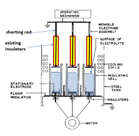
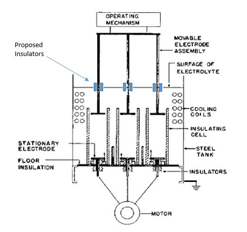
The company performing the overhaul are proposing to insulate the moving electrodes from earth (other that the resistance through the electrolyte)
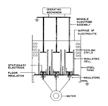
existing_sfdwaj.jpg
Existing

proposed_tg30ii.jpg
Proposed

We have five liquid starters and have been in operation since circa. 1970 without and significant issues. The original manufactures (Allen West) documentation Leaflet 909/A/3 that states “Neutral or Star point is earthed, so that the rotor slip rings must be insulated from earth” In this case the motor winding are insulated from earth.

MOTOR DETAILS
MANUFACTURER Harland and Wolff
TYPE Slip Ring Induction
OUTPUT 1200
RATED SPEED 1480
RATED VOLTAGE 6600
RATED CURRENT 91
PHASE 3
FREQUENCY 50
POLES 4
CONNECTION Y
ROTOR S.R.
ROTOR VOLTS 1310
ROTOR CURRENT 418
INSULATION CLASS B
FRAME A40/60
STANDARD BS 2613

LIQUID STARTER DETAILS
The motor operated Liquid Starters were manufactured by Allen West & Co Ltd, Brighton, model TS5.
Each Liquid Starter is controlled via existing relay and timer logic implemented within the pump-house control console and respective MV motor starter.
Each of the units have been subject to periodic checking and adjustment of electrolyte level and concentration.

My question being, that if the star point is insulated from earth what happen if we lose a rotor winding and the circuit goes out of balance? Is this potentially dangerous?
 
Replies continue below

Recommended for you

After 45 years of service they claim that the OEM did it wrong?
Good enough for another 45 years is not good enough?
I haven't worked on liquid rheostat starters for almost 50 years.
We were starting pairs of 3000 HP motors at 13,000 Volts.
Once the shorting contactor closed the rheostat contactor opened.
There were six pairs of motors and three liquid rheostats. (One spare.)
A large contactor panel allowed any rheostat to be connected to any motor for starting.

The movable electrode assembly of the Allen West liquid rheostat for the start point that is mentioned in the Allen West brochure.
It is grounded as it should be.
To insulate the mechanism and movable electrodes would be against the OEM's original intent.
It ain't broke. Don't fix it.

There should be a starting contactor that takes the liquid rheostat out of the circuit once the motor is up to speed.

Loss of a rotor winding renders the motor unservicable.
You will have high slip, high current and probably overheating of both the stator and the rotor.
You may have increased vibration.

Bill
--------------------
"Why not the best?"
Jimmy Carter
 
Have you given any thought to using regenerative circuitry to start/control the motors instead of liquid rheostats? Significant energy savings can be achieved.

CR

"As iron sharpens iron, so one person sharpens another." [Proverbs 27:17, NIV]
 
Hi CR, I saw some of the first regenerative circuits used for speed control of fans.
For continuous service there was a recognized saving over resistors in the rotor circuits of WR motors.
There were added tax incentives for a recognized energy saving device.
For starting duty, the time in seconds per day is so little that the payback on the capital investment may stretch into centuries.
There may be some maintenance savings down the road.

Bill
--------------------
"Why not the best?"
Jimmy Carter
 
I see no electrical reason for those insulators. If the electrodes were wobbling while moving up & down, then the insulators could act as 'guide bearings', I suppose.

As Bill said, let sleeping dogs lie.

Muthu
 
Many thanks for the replies.

I think its safe to say that I will be advising them to leave the starters as they are, like most I don't see any reason to add the insulators!

Thanks,

Robert

 
Leave the grounds on the lifting mechanism in place as per the brochure.
That is the grounded wye point.

Bill
--------------------
"Why not the best?"
Jimmy Carter
 
The overhaul is legitimated only if you purchase a frequency converter .
Good luck !
 
Yes, if they don't have a good technical reason then leave it as is.
 
In my opinion, the surface of the electrolyte has to be inside the insulated cell, otherwise, the common electrolyte will cause a short circuit. In order to control the height of liquid per phase the shorting rod of each phase of operating mechanism must be insulated.
Rotor_liquid_resistors_w83s5g.jpg
 
The liquid can't short the rods together since they are already solidly shorted together outside of the tank.
 
What Lionel said.
The current path is from the tank bottom electrode to the suspended electrode.
Very little if any current reaches the rods.
But, what do the existing, 50 year old rods look like?
If they are still serviceable after 50 years then new rods should be good for 30 or 40 years without insulators.
If you do go for insulation, no need for anything expensive.
sections of ABS or PVC pipe of the approximate diameter should suffice.
As far as the electrolyte shorting the sections, the liquid rheostat that I installed many years ago had a common reservoir across the tops of the three cylinders.
The electrolyte was circulated by a pump from the top reservoir to the bottoms of the three sections to aid in removing heat and to avoid boiling the electrolyte.
Bill
--------------------
"Why not the best?"
Jimmy Carter
 
As always in these fora, I have learned much in this thread; thank you, contributors all.

I especially appreciate your comment, Bill, that if the liquid rheostat is for starting purposes only, the energy recovery is much less than if speed control is also performed, particularly if the number of starts is limited and the starting period relatively short...

It might be helpful to mention that my experience with liquid rheostats was in running up decoupled 160 MVAR generators from turning gear to synchronous speed for use as spinning VAR resources for the grid; the run-up time took from fifteen to twenty minutes, which might have justified newer technology if the writing hadn't already been on the wall for that plant...

The liquid rheostat was unpumped, instead relying on convection and baffling to circulate the electrolyte around the cooling water pipes positioned on the inner periphery of the one large cylindrical tank containing the unit; raw water was used as the cooling medium, and a motorized valve controlled the flow of raw water based on the pallet contacts of specific breakers in the starting circuitry. The thermal mass of the rheostat was good for two consecutive starts, which was all that was generally needed since only two of the eight-unit plant's alternators had been decoupled from their steam turbines for use as synchronous condensers. If however both units were scheduled to be on line and one experienced any trip or other trouble during any run-up, time might have to be allowed for the electrolyte to cool enough for another try lest boiling commence, particularly when it wasn't winter and the cooling water wasn't barely above freezing temperature, and during the summer was when the units were most often used for reactive support when the air conditioning load of the adjacent downtown core was quite heavy.

By the time I left that location the entire plant was slated for demolition within five years, and as there were multiple copies of the schematics and run-up instructions lying about, I retained copies of both for future reference and for personal interest; I still have them.

CR

"As iron sharpens iron, so one person sharpens another." [Proverbs 27:17, NIV]
 
Was the liquid rheostat connected in the wye point of the generator windings?
That's the only way that I can see that a common tank liquid rheostat can start a synchronous motor/generator.
Maybe I'll learn something new today. grin

Bill
--------------------
"Why not the best?"
Jimmy Carter
 
crs

"running up decoupled 160 MVAR generators from turning gear to synchronous speed for use as spinning VAR resources for the grid"

Interesting. But aren't the turning gears typically stepped down to 30-50 RPM generator speed requiring typically low HP, 4 to 6 pole motors? How did you use the turning gear to step up to the synch speed? Was the original turning gear and motor replaced for the condenser mode operation?

Muthu
 
I'm typing this between and around other business; pls excuse typos.

It wasn't that straightforward, Bill...

Units were built as tandem compound high and low pressure steam-turbine-driven units, and therefore had one high-speed [ 3600 rpm ] and one low-speed [1800 rpm ] alternator, each rated @ 80 MVA. Alternator terminals were solidly connected to an isolated phase bus [ IPB ] which fed the unit's power to an MOT [ 13.8 kV > 115 kV ] ; there were also two unit station service transformers [ 13.8 kV > 4160V ] connected to the IPB, intended to supply that unit's internal load when generating, and enabling it, if tripped off line, to survive system disturbances carrying its own station service loads.

Special circuitry enabled a pony run-up set, consisting of a 1300 HP five-pole-sets 4160V wound-rotor induction motor [ this is where the liquid rheostat was used ] driving a six-pole 13.8 kV synchronous generator, to be connected to the IPB of the unit to be run up. [ At the risk of stating the obvious, the difference in the number of poles between the pony motor and generator was what enabled the HP/LP line to be brought up to [ and over actually, reach full synchronous speed. ]

[ I'd hoped to include a schematic, but we're under reduced staffing today [ COVID-19 fallout - due to pre-emptive location segregation, not illness ] , and because I'd need the assistance of others was unable to; I can still try to do so in the future if there's enough interest. ]

Sequence was roughly and rudimentarily as follows:

Exciter MGs for the HP and LP generators were started, field breakers closed, and excitation slowly applied to the generators until there was sufficient magnetic coupling to lock them into synchronism; the "gear ratios" of the turning gears were not precisely matched, and once the two generators locked into synchronism the HP generator's higher speed generally, but not always, caused its speed to exceed the turning gear speed, meaning the Bendix mechanism within the turning gear would slowly back the pinion gear of the drive out from fully home until a microswitch picked up this spline shift and tripped the HP turning gear off, leaving the LP turning gear driving both machines.

The MG exciter for the pony set was started next, and field slowly applied to the pony generator until it was pulled from rest and locked itself into sync with the HP and LP machines.

Sufficient excitation was then applied to the HP, LP and pony machines to ensure no pole slip occurred, following which [ once the liquid rheostat resistance was confirmed to be at maximum ] the supply breaker to the pony motor was closed, and run-up would commence, with the liquid rheostat yoke being lowered, and wound-rotor field circuit resistance therefore being slowly decreased, so as to maintain rated full load pony motor current as the run-up proceeded.

The rate of acceleration of the line slowed noticeably as the windage losses of the generator-shaft-mounted hydrogen circulating fans built up; more excitation was applied to all three machines as run-up proceeded [ respecting V/Hz ratio ] .

Machine line-up was brought to speed and generators synchronized to the grid, then liquid rheostat was backed off, pony motor supply breaker opened, pony generator output breaker opened, and pony set line-up prepared for start of next machine run-up or secured, whichever was applicable. At this point excitation on the now-synchronized HP and LP machines was selected from manual to AVR control, the condenser was released to the IESO for system deployment, and AVR setpoints adjusted as required.

Faulty memory, btw; @ 90°F a solenoid-operated cooling water valve opened, and @ 160°F an electrolyte high temp alarm would be received. Cursory re-reading of the start-up sequence suggests this alarm had to be clear before a run-up sequence could be initiated.

Because this was the means used to run decoupled generators up to speed, any of the eight units in the plant could theoretically have been used as synchronous condensers, but the wiring changes needed for this were only ever applied to two units.

Hope all this makes sense.

CR

"As iron sharpens iron, so one person sharpens another." [Proverbs 27:17, NIV]
 
Hey edison123,

The quote was "running up decoupled 160 MVAR generators FROM turning gear to synchronous speed," not "running up decoupled 160 MVAR generators WITH turning gear to synchronous speed."

Maybe I'm being a PB [picky bastard], but words matter.

CR

"As iron sharpens iron, so one person sharpens another." [Proverbs 27:17, NIV]
 
Thanks CR.

Bill
--------------------
"Why not the best?"
Jimmy Carter
 
Status
Not open for further replies.

Part and Inventory Search

Sponsor