Continue to Site

Eng-Tips is the largest engineering community on the Internet

Intelligent Work Forums for Engineering Professionals

  • Congratulations GregLocock on being selected by the Eng-Tips community for having the most helpful posts in the forums last week. Way to Go!

6ft foundation wall on piles

Status
Not open for further replies.

Serhiy

Structural
May 10, 2018
14
Good day. I'm going to design a building with 6ft cantilevered foundation wall supported by cast in place piles. Foundation wall will support wood studwall. Loads are not going to be huge (building is 40ft wide). I'm wondering how to approach wall and wall-to-pile connection design. I assume piles will be spaced at around 16ft on centre. I was planning to design wall to take out of plane moment due to wind and axial due to dead/snow load. One concern is that wall is not fully supported at the base and now there will be warping/torsional distortion mid-way between piles due to combined wind and axial forces. How do I account for it in my design? Appreciate any comments. Thanks
 
Replies continue below

Recommended for you

Without getting into bi-axial bending analysis or a finite element model, you can design it for bending in each direction independently. Assume each pile carries the loads on its tributary width of the wall and carry it to the pile. Then design the wall as a very wide, shallow, continuous beam. It's going to be very conservative, but weigh the cost of reinforcing against that for an FEM or the time it will take to do an in-depth biaxial analysis, and I'll bet the extra rebar will start to look pretty cheap.

In a pinch, we generally assume forces spread through concrete at a 45 degree angle, so for a 6ft high wall, the force at the pile connection will be fully distributed through the height of the wall at 6ft horizontally from the pile. You'll need heavier reinforcement horizontal near the bottom on the outside face of the wall near the piles.

All of the above assumes you don't have a strip footing attaching to the piles and wall. With that the main concern is getting adequate development of the pile reinforcement into the footing. You'll have to consider torsion on the footing, also. I could point you to articles of the AASHTO bridge design spec. for calculating torsion capacity, but I'm sure you'd be better served using whatever spec. you're designing to.
 
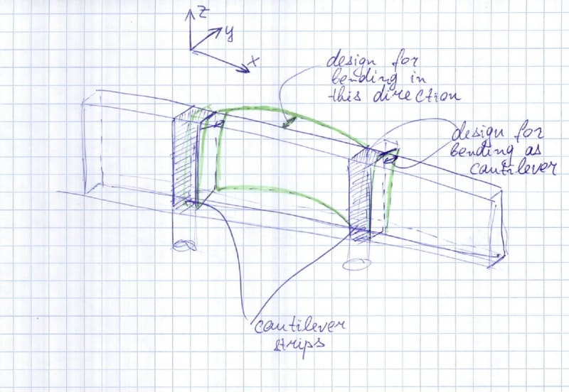
Thanks for reply, HotRod10. As I understood you are suggesting to analyze/design wall as spanning horizontally between piles (y direction as per my sketch) and then design vertical strips extending straight up from piles as cantilever beams that would bring load and moment to piles. Please see my sketch that illustrates my understanding of the approach you suggest
Untitled_reny0x.jpg
:

This approach would work if lateral load was applied as uniform surface load. The problem with it in my case is that my lateral load from studwall is applied as a line load along the top of the wall. That will cause top strip of the wall to be subjected to higher bending moment (out of plane) than the lower strips of the wall. I could design the top strip to carry all the bending from top line load but what would be the reasonable width of such strip to assume? Also, would I need to design it for torsion?

Regarding the bottom reinforcement I agree that this wall most likely will act as deep beam so I'm going to design it for in-plane bending accordingly.

Also, for your information I don't have footings.

I usually use Risa 3D for structural steel design and checked some videos on wall design as well and it didn't seem that complicated. Maybe I will give it a try designing my wall in it.

Thanks
 
Your sketched analysis model is not exactly what I envisioned, but basically the same. I would give consideration to the load spreading laterally from the piles as you go up the wall. It's fine to analyze it as if the load stays concentrated above the pile for design of the reinforcing in the wall directly above the pile, but I would assume a wider distribution in designing the vertical reinforcing in the remainder of the wall. It's an envelope approach of sorts - assuming the worst case for each section, since we don't know (without a detailed analysis) how the loads will distribute through the wall.

I assumed that your out-of-plane loading to the top of the wall would be of a similar magnitude as the soil pressure load, which would be greater towards the bottom. If the loading to the top is significantly larger, it would be prudent, as you said, to consider less than the full height of the wall resisting in horizontal bending. Given the 16ft span, engaging 2-3 ft vertically seems at least reasonable, if not greatly conservative. For the couple of wall-type structures of we've analyzed, using the 45 degree rule was fairly conservative compared to the FEM results. Since it's 8ft horizontal from the center of the span to the support and only 6ft vertical, you would likely be fine assuming the full depth is engaged.
 
Status
Not open for further replies.

Part and Inventory Search

Sponsor