Power Supply:
Gophertc CPS-6011
60V 11A Adjustable C/V.
LED’s:
108x Cree XP-G3
LED Configuration:
6x 18 LEDs in Series.

XP-G3 LED's = (2.74 Vf 150mA @25C) - (3.11 Vf 2000mA @25C)
Voltage Range = 49.32 to 55.98v
49.32v + .2 Transistor drop = 49.52v
BD139 Transistors have Maximum Collector-Emitter Voltage of 80.
Max Collector Current (DC) = 1.5A
The Minimum Voltage could be about 50v up to the Supplies Maximum of 60v!

Work out Voltage at V1
V1 = Resistor1 x 1.1A
Bipoloar NPN transistors 0.7v drop across.
0.7v. R1 = (0.7v / 1.05A) = 0.6666666666666667 ohms.
The voltage at the anode of D7 will be (2 * 0.7v) or 1.4v.
1mA down through diodes should bias them to the 0.7v on state.
0.5mA to bias each transistors well into saturation point, turned on.
6 Transistors = 3mA current
1mA through D7/D8 Diodes + 3mA for Transistors.
4mA of current required through Rr.
Rr can be calculated as (53.64v -1.4v Diode drop) / 0.0040A = 13.060 ohms.
-----------------------
Resettable Breakers
I have a 60V 11A adjustable Power Supply and wanted to safeguard against someone adjusting to 11A and blowing up Current Balancing Transistors.
Thermal Derating Curve
You will see below the Raychem RXE-065S1 trigger current changes 19% between 20 and 40C Ambient Temperatures.
The Littlefuse RKEF065 has very similar specs with tighter trigger Current variation of 13% over 20 to 40C Ambient Temperatures.
Time-to-trip
The other thing is time to trip in seconds, the RXE-065S1 is more like a Slow Burn Fuse at 5.3 Sec.
Which makes me think this might not be suitable for my purpose, but would protect from a slowly rising current?
The RKEF065 has a faster, 1 second trip time.
But would it trip before damage if someone dialed up the current on Power Supply.
Anybody know?
-
Here's some Specs for those who are interested, 40C Trip Currents are derived from graph - double check with data sheets before use.
-------
RXE-065S1 60V - Raychem
% of rated hold and trip current for Ambient Tempretures.
Thermal Derating Curve (81% of hold and trip @40C)
Hold Current (A) 0.65 @20C
Hold Current (A) 0.47 @40C
Trip Current (A) 1.3 @20C
Trip Current (A) 1.053 @40C
Time-to-trip 5.3 Sec
Time-to-trip with Fault Current of 10A = .1 Sec
Min Resistance 0.31 Ohm
Max Resistance 0.48 Ohm
---------------------------------
RKEF065 60V - TE Connectivity or Littlefuse
% of rated hold and trip current for Ambient Tempretures.
Thermal Derating Curve (87% of hold and trip @40C)
Hold Current (A) 0.65 @20C
Hold Current (A) 0.54 @40C
Trip Current (A) 1.30 @20C
Trip Current (A) 1.131 @40C
Time-to-trip 1.0 Sec
Time-to-trip with Fault Current of 10A = .09 Sec
Min Resistance 0.250 Ohm
Max Resistance 0.450 Ohm
---------------------------------
RKEF050 60V - TE Connectivity or Littlefuse
% of rated hold and trip current for Ambient Tempretures.
Thermal Derating Curve (87% of hold and trip @40C)
Hold Current (A) 0.50 @20C
Hold Current (A) 0.38 @40C
Trip Current (A) 1.00 @20C
Trip Current (A) 0.87 @40C
Time-to-trip 0.8 Sec
Time-to-trip with Fault Current of 10A = .06 Sec
Min Resistance 0.320 Ohm
Max Resistance 0.529 Ohm
----------------------------------------------------------------------------------
Brief Explanation:
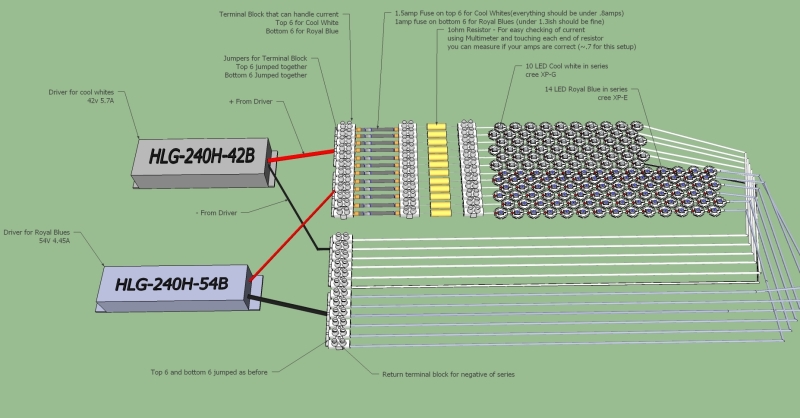
Basically we have 6 strings of 18 LED's each.
Each set of 18 LED's uses 1050mA and has a Current limiting Transistor.
The power supply is 11A max, hence it is capable of providing 1.83A per string of 18 LED's.
As a precaution, I am looking at protect each string from exceeding about 1.3A Current.
Questions:
Current Balancing Transistors?
Can anybody help with BD139 Transistors alternative?
I need 6 Transistors in a single package for the thermal connection properties!
PolySwitches?
Anybody using these Polyswitches, do you have a known Source Current reference to give some real world experience.
A device like RXE-065S1 would be perfect If the trip Current stayed within the 1.3 to 1.053 Amp variation (20 to 40C).
But when the Data sheet mentions Min Hold Current is 0.65A and Max Trip Current is 1.3A there is a very large gap between.
So the question is, how tight is the Trip Current in real use.
The RKEF065 has a faster, 1 second trip time but would it trip before damage if someone dialed up the current on Power Supply. Anybody know?
Gophertc CPS-6011
60V 11A Adjustable C/V.
LED’s:
108x Cree XP-G3
LED Configuration:
6x 18 LEDs in Series.
XP-G3 LED's = (2.74 Vf 150mA @25C) - (3.11 Vf 2000mA @25C)
Voltage Range = 49.32 to 55.98v
49.32v + .2 Transistor drop = 49.52v
BD139 Transistors have Maximum Collector-Emitter Voltage of 80.
Max Collector Current (DC) = 1.5A
The Minimum Voltage could be about 50v up to the Supplies Maximum of 60v!
Work out Voltage at V1
V1 = Resistor1 x 1.1A
Bipoloar NPN transistors 0.7v drop across.
0.7v. R1 = (0.7v / 1.05A) = 0.6666666666666667 ohms.
The voltage at the anode of D7 will be (2 * 0.7v) or 1.4v.
1mA down through diodes should bias them to the 0.7v on state.
0.5mA to bias each transistors well into saturation point, turned on.
6 Transistors = 3mA current
1mA through D7/D8 Diodes + 3mA for Transistors.
4mA of current required through Rr.
Rr can be calculated as (53.64v -1.4v Diode drop) / 0.0040A = 13.060 ohms.
-----------------------
Resettable Breakers
I have a 60V 11A adjustable Power Supply and wanted to safeguard against someone adjusting to 11A and blowing up Current Balancing Transistors.
Thermal Derating Curve
You will see below the Raychem RXE-065S1 trigger current changes 19% between 20 and 40C Ambient Temperatures.
The Littlefuse RKEF065 has very similar specs with tighter trigger Current variation of 13% over 20 to 40C Ambient Temperatures.
Time-to-trip
The other thing is time to trip in seconds, the RXE-065S1 is more like a Slow Burn Fuse at 5.3 Sec.
Which makes me think this might not be suitable for my purpose, but would protect from a slowly rising current?
The RKEF065 has a faster, 1 second trip time.
But would it trip before damage if someone dialed up the current on Power Supply.
Anybody know?
-
Here's some Specs for those who are interested, 40C Trip Currents are derived from graph - double check with data sheets before use.
-------
RXE-065S1 60V - Raychem
% of rated hold and trip current for Ambient Tempretures.
Thermal Derating Curve (81% of hold and trip @40C)
Hold Current (A) 0.65 @20C
Hold Current (A) 0.47 @40C
Trip Current (A) 1.3 @20C
Trip Current (A) 1.053 @40C
Time-to-trip 5.3 Sec
Time-to-trip with Fault Current of 10A = .1 Sec
Min Resistance 0.31 Ohm
Max Resistance 0.48 Ohm
---------------------------------
RKEF065 60V - TE Connectivity or Littlefuse
% of rated hold and trip current for Ambient Tempretures.
Thermal Derating Curve (87% of hold and trip @40C)
Hold Current (A) 0.65 @20C
Hold Current (A) 0.54 @40C
Trip Current (A) 1.30 @20C
Trip Current (A) 1.131 @40C
Time-to-trip 1.0 Sec
Time-to-trip with Fault Current of 10A = .09 Sec
Min Resistance 0.250 Ohm
Max Resistance 0.450 Ohm
---------------------------------
RKEF050 60V - TE Connectivity or Littlefuse
% of rated hold and trip current for Ambient Tempretures.
Thermal Derating Curve (87% of hold and trip @40C)
Hold Current (A) 0.50 @20C
Hold Current (A) 0.38 @40C
Trip Current (A) 1.00 @20C
Trip Current (A) 0.87 @40C
Time-to-trip 0.8 Sec
Time-to-trip with Fault Current of 10A = .06 Sec
Min Resistance 0.320 Ohm
Max Resistance 0.529 Ohm
----------------------------------------------------------------------------------
Brief Explanation:
Basically we have 6 strings of 18 LED's each.
Each set of 18 LED's uses 1050mA and has a Current limiting Transistor.
The power supply is 11A max, hence it is capable of providing 1.83A per string of 18 LED's.
As a precaution, I am looking at protect each string from exceeding about 1.3A Current.
Questions:
Current Balancing Transistors?
Can anybody help with BD139 Transistors alternative?
I need 6 Transistors in a single package for the thermal connection properties!
PolySwitches?
Anybody using these Polyswitches, do you have a known Source Current reference to give some real world experience.
A device like RXE-065S1 would be perfect If the trip Current stayed within the 1.3 to 1.053 Amp variation (20 to 40C).
But when the Data sheet mentions Min Hold Current is 0.65A and Max Trip Current is 1.3A there is a very large gap between.
So the question is, how tight is the Trip Current in real use.
The RKEF065 has a faster, 1 second trip time but would it trip before damage if someone dialed up the current on Power Supply. Anybody know?