Continue to Site

Eng-Tips is the largest engineering community on the Internet

Intelligent Work Forums for Engineering Professionals

  • Congratulations Danlap on being selected by the Eng-Tips community for having the most helpful posts in the forums last week. Way to Go!

A modular profile (item) construction - tolerances?

elinah34

Mechanical
Aug 19, 2014
145
Hello,

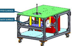
This is the first time I draw a modular profile (item) construction. What type of tolerances (and values range) is acceptable and reasonable?
I guess that size tolerances are OK, but what about the required precision?
If I want profiles to be parallel to each other, can I require it and on the same time avoid "no bid" by manufacturers?
I am very experienced in machining and know what precisiona can be achieved, but in this case (assembled modular profiles) I am not sure what and how can be achieved.

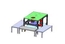
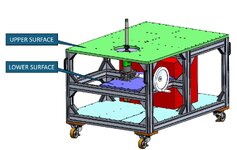
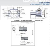
I am adding pictures for illustration.
image029[1222].png
QA11083A.JPG
 
Last edited:
Replies continue below

Recommended for you

Op
Get back to basics like squaring a block, or Machining a plate parallel and flat. But it will not happen with caster wheels installed.
It can be made parallel to each other but not to the floor.
I would machine the top and bottom frames
Parallel. Then machine the blue colored plate .
And must have access for tooling.
 
Last edited:
Hey, I don't really care about being parallel to the floor. I am more interested in parallelism of the bog green plate to the small purple.
 
I would to spot face the purple with a fly cutter. if the entire surface does not require parallel.
 
I am adding a CAD model, maybe it can help.
 

Attachments

  • QA11083A.zip
    8.1 MB · Views: 0
Have you identified parallel within WHAT? What do you NEED?
I need both surfaces to be parallel to each other.
It depends on the parallelism of the plates surfaces, but it also depends on the parallelism of the profiles the plates rest on.
1.JPG

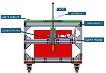
The real motivation (based on several different tolerances that accumulates) is making the rod being perpendicular to the Upper surface.
I know 90 degrees can't be achieved, and I am trying to find out what is the real range based on a reasonable tolerances of the relevant parts.
2.JPG
 
I bothers me when I hear non-engineers say something like "its got to be parallel". I have to explain there's no such thing as just "parallel". The word requires a measurement. How parallel? But when I hear engineers say that... well... we won't go there.

How parallel do you need it?

No matter how "parallel" it has to be, bolted extrusion profiles are NOT the way to achieve that. Even if the frame is assembled perfectly, the delivery truck hits a good bump, and there goes your parallelism. Extrusion profiles are great. I use them all the time. But they're just not stiff and immune to damage like a weldment. The whole thing doesn't have to be welded but you probably want a welded and machined frame at least between those two critical surfaces to firmly establish their relationship regardless of what happens elsewhere in the structure.
 
Parallel when? Under loading, or at assembly? It seems like the best way to control the parallelism is to mount the mechanism to the same green plate.

Why not ask the 80/20 applications engineer about this and seek recommendations - https://8020.net/design-assistance
 
OP
I suggest grab the drawing and visit 3 machine shop suppliers and showcase your 3 d drawings.

The supplier requires a large vertical machining center old style , with out guards. That can sink a machining spindle down the hole . Machine by interpolation . Maximum radius permitted by the hole diameter. And the largest radius tool cutter
Thatwill fit. Prior to assembly the purple plate will require machining to leave a raised step. That can be machined after assembly.
If both plates are machined at the same setup.
Parallelism can easily be achieved.
I would said at least .020 inch tolerance.
Machine only what is required to fit the gear box.
Don't you think that a mutual machining may make the manufacturing process complicated?
I assumed (by making rough calculations in the beginning) that a parallelism of 1 mm between the two planar aurfaces can be required and achieved.
 
Parallel when? Under loading, or at assembly? It seems like the best way to control the parallelism is to mount the mechanism to the same green plate.

Why not ask the 80/20 applications engineer about this and seek recommendations - https://8020.net/design-assistance
You wrote an interesting point "mount the mechanism on the same green plate. Any idea how to actually Simply make it without changing the design
OP
Not at all, and it done often
And there is no way of getting 1 mm parallelism without mutual machining? In addition, if mutual machining is done, the change over time (due to transportation vibrations, shocks etc.) will be significant or relatively negligible?
 
You wrote an interesting point "mount the mechanism on the same green plate. Any idea how to actually Simply make it without changing the design

And there is no way of getting 1 mm parallelism without mutual machining? In addition, if mutual machining is done, the change over time (due to transportation vibrations, shocks etc.) will be significant or relatively negligible?
OP
Yes buy using a .0005 precision inch level. During assembly place the level on the plate.
Add shim stock between mounting surface and plate. Until level is flat. The plates will require pre machined and ground by double disk grind.
Shim stock can be purchased from online suppliers at different precision thickness.
If there is access to laser or optics. Plates can also be leveled by optics as well.
 
Any idea how to actually Simply make it without changing the design
My first thought would be that instead of mounting the purple plate to the horizontal 80/20 pieces, that you mount it to the underside of the green plate with some large standoffs/posts, vaguely as shown below with the yellow rectangles (I'd use 4 posts, but I only drew 3 since they overlap). Since you're only looking for 1mm of parallelism, if all of the interfaces are toleranced (you'll have to do some work to figure those out) and machined properly, and the posts are all close enough in length, you might be able to get away with bolting the whole thing together rather than welding and then machining. If shimming the posts is acceptable, then you've got more wiggle room on the tolerances. Of course, the higher the purple plate can go, the better. I'm assuming this thing is relatively lightly loaded. If it has large loads on it (particularly horizontal loads), then I probably wouldn't go this route or would modify it.

1739998676184.png
 
OP
Yes buy using a .0005 precision inch level. During assembly place the level on the plate.
Add shim stock between mounting surface and plate. Until level is flat. The plates will require pre machined and ground by double disk grind.
Shim stock can be purchased from online suppliers at different precision thickness.
If there is access to laser or optics. Plates can also be leveled by optics as well.
Thanks
 
My first thought would be that instead of mounting the purple plate to the horizontal 80/20 pieces, that you mount it to the underside of the green plate with some large standoffs/posts, vaguely as shown below with the yellow rectangles (I'd use 4 posts, but I only drew 3 since they overlap). Since you're only looking for 1mm of parallelism, if all of the interfaces are toleranced (you'll have to do some work to figure those out) and machined properly, and the posts are all close enough in length, you might be able to get away with bolting the whole thing together rather than welding and then machining. If shimming the posts is acceptable, then you've got more wiggle room on the tolerances. Of course, the higher the purple plate can go, the better. I'm assuming this thing is relatively lightly loaded. If it has large loads on it (particularly horizontal loads), then I probably wouldn't go this route or would modify it.

View attachment 5162
Thanks
 
Assuming that this is a screw jack of some sort, it would be fairly simple to mount an inverted jack to the underside of the green plate. It may be necessary to use a spacer plate. Without more information on the device it is hard to provide more assistance.

duff norton.JPG
 

Part and Inventory Search

Sponsor