Continue to Site

Eng-Tips is the largest engineering community on the Internet

Intelligent Work Forums for Engineering Professionals

  • Congratulations IDS on being selected by the Eng-Tips community for having the most helpful posts in the forums last week. Way to Go!

A question about Voltage Regulation for transformers 2

Status
Not open for further replies.

bdn2004

Electrical
Jan 27, 2007
794
I'm reading in this book "Handbook of Practical Electrical Design" the following statement:

"Voltage regulation is another transformer consideration, and impedance is related to it. Voltage regulation is the measure of how the secondary voltage of a transformer varies as the load on the transformer varies from full load to zero, with the primary voltage held constant.

Voltage regulation is expressed as a percentage that is calculated as the no-load voltage minus the full-load voltage divided by the full load voltage times 100 percent. For example, if a transformer has no-load secondary voltage of 240V, and the voltage drops to 220V the the regulation percentage - (240-220)/220 x 100 percent = 9%.

This indicates that 9% of the secondary voltage is being dropped across the internal impedance of the transformer. It is obvious, then, that the higher the impedance of the transformer, the greater the drop from no-load to full-load voltage and the higher the regulation. It is generally desirable to keep regulation as low as possible, to minimize variations in voltage as load-current demand varies. Typical regulation values are between 2 and 4 percent."

MY QUESTION: How EXACTLY is the voltage regulation determined in relation to the impedance? Is this a factory or a measured number? The above statement says "the impedance is related to it....". Related how?

I'm asking this as we are considering placing a long feeder, that shows a voltage drop issue and feeds a 480V-120/208Y transformer onto one of it's lower 2-1/2% primary taps.
The concern is we don't want to over voltage the secondary.
 
Replies continue below

Recommended for you

It's just the voltage drop across the transformer. You can calculate it if you know the reactance and approximate resistance of the transformer windings. But it's a phasor calculation and also depends on the power factor of the load.
 
Most people don't think about a voltage drop on a step down transformer, but when you look at it as a percentage of normal, and factor in the impedance in the transformer, the more load flow through the transformer (or line for that matter), the more voltage difference you will see across it. But that fact that the voltage on the two sides is always different, you must look at percent to normal to understand the drop.
 
The reactive portion of the load current produces a reactive voltage drop across the reactive portion of the transformer's impedance while the resistive portion of the load current produces a resistive voltage drop across the resistive portion of the transformer's impedance. For larger transformers the impedances is nearly all reactive and the load nearly all resistive and the resulting voltage drop is small compared to the impedance; regulation numbers much smaller than impedance numbers. For small transformers the resistive component of the impedance can be a significant fraction and the load will produce a much higher voltage drop; regulation numbers approaching impedance numbers.

I’ll see your silver lining and raise you two black clouds. - Protection Operations
 
In IEEE Std 12.90-2010, the exact formula for calculating regulation is:

a) When the load is lagging: reg=sqrt[(R+Fp)^2 + (X+q)^2]-1
b) When the load is leading: reg=sqrt[(R+Fp)^2 + (X-q)^2)]-1

Fp is power factor of the load in pu
q is + sqrt(1-Fp^2)
R is resistance factor of transformer = (load loss in kW)/(rated kVA)
X is reactance factor of transformer = + sqrt(Z^2-R^2)

quantities are in per unit
 
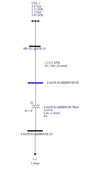
Thanks for the good answers. Just for future reference...Here is a slide of the installation I'm looking at. I made the Utility from the SC data at that point in the system.

Voltage_Regulation_Slide_1_mvyaoe.jpg
 
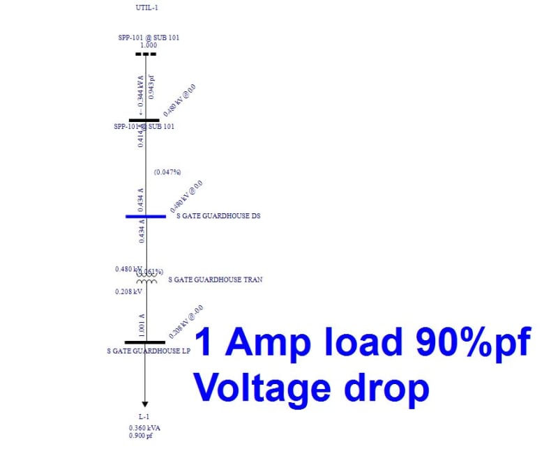
1 amp load with a 90% power factor

Voltage_Regulation_Slide_2_gng1eo.jpg
 
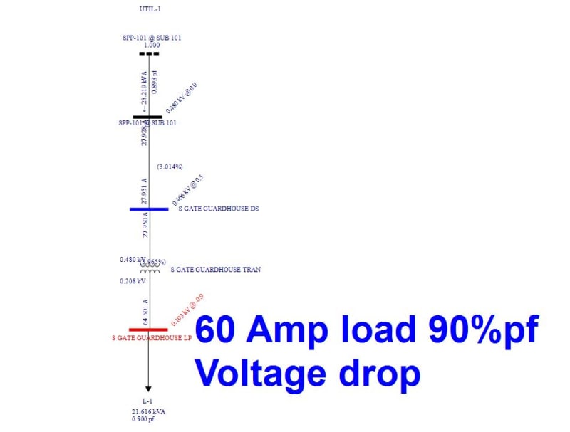
And a 60Amp load 90% power factor

Voltage_Regulation_Slide_3_azchzl.jpg
 
Calculating the Short Circuit current is simple. Just use the %impedance.
Calculating the voltage drop at a resistive load is easy. Just use the % regulation.
Calculating the voltage drop at a non unity PF, you must consider the transformer resistance, the transformer inductive reactance, the load resistance and the load inductive reactance.
The result will be somewhere in between the %imp and the %regulation.
A short cut is to use the %impedance to calculate the worst case* Voltage drop. If that is acceptable, you do not need to do the more rigorous calculation.
* An exception to the worst case may be when calculating the voltage drop caused by the magnetizing current when feeding a transformer with a higher X:R ratio than the supply transformer. However in this case the current would be expected to be a very small percentage of full load current.
This would be an issue only if an very accurate calculation of the open circuit voltage was required.
The error would be a very small percentage of a very small percentage of a small number.

Bill
--------------------
"Why not the best?"
Jimmy Carter
 
Ok based on my plots above:

Voltage at No load = 208V
Voltage at 60A ... about 75% load: 193V

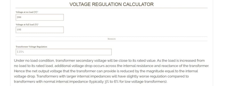
(V_nl - V_load)/V_load x 100 = [(208 - 193)/193] x 100 = 7.77%

This agrees with that web site calculator...

Voltage_Regulation_Slide_4_lxfs5f.jpg


But that doesn't agree with my book...that most transformers are between 2-4%.
That 6% transformer is not helping things it appears.
 
The exact formula for voltage regulation in transformer is
kpR+kqX+(kpX-kqR)2/2

where k= actual load as per unit of rated or base power rating
p= power factor
q =+- square root of(1-p2)
R= per unit resistance (load loss/ rated power)
x=per unit reactance
1) at Unity power factor, if second term is neglected, (as suggested by waross) error can be appreciable esp for large transformers with high X
2) Voltage regulation increases with load, decreases with increasing power factor.
3)Jghrist, can you give the clause number of standard. I find it bit strange.
 
Jghrist, I got it -clause14.4.4.1. Interesting point is there is another general formula in Cluase14.4.4.1 that give much more accuracy. Frankly this never came to my notice though handling C57 for many decades. Learning something new everyday ! Thank you Jghrist!!Incidentally,C57.90 revised in 2015.

I am wondering the reference and derivation for the formula as per IEEE. I never came across it in literature or text book. The formula that I mentioned is the classic one and derivation is there in Transformer text book by L F Blume.(1939).

I took an example. A transformer with R=0.005 X=0.09 at unity power factor. Both formulae gave Reg of 0.9% at unity power factor.


Status
Not open for further replies.

Part and Inventory Search

Sponsor