xMeck
Electrical
- Nov 5, 2019
- 9
So I am going to be posting this in both the mechanical and electrical section as I wasn't sure which would be able to help with this question as it could fall under both sides in a way. But my question is about a mechanical load block diagram which I need to make, I currently have a diagram drawn up on paper but I have no idea how to replicate some parts into PLECS as I cannot find the blocks able to use.
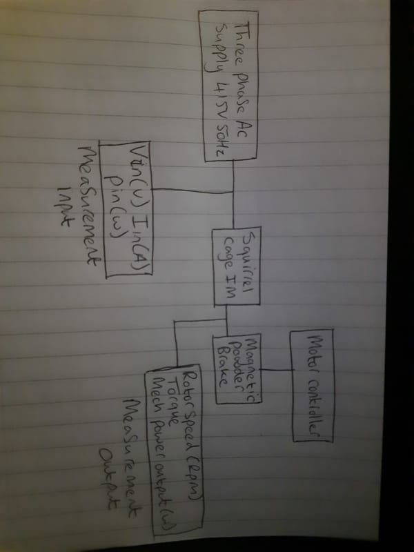
I will post the image below of my drawn up system and what I am using, the main block I am having issues finding/replacing with something else is the magnetic powder break. I have my three phase supply connected up to my three phase squirrel cage motor currently, I haven't yet added the measurements for the inputs and have been trying to find out what I can use for the motor brake before I move onto adding the output measurements. Along with the powder brake what could I use in PLECS as a controller to control the set point of the motor break which will give me a change in results.
If anyone was interested in how the system should work ill give it a quick rundown. I am going to have my three phase ac supply connecting to the stator windings of my squirrel cage induction motor, in between the motor and supply I want to have my measurement devices reading the input values, this will be the usual power, voltage and current readings. I will then connect the squirrel cage motor up to a magnetic powder break which basically just slows down the motor using the powder inside combined with the increase of current on the magnetic field, for this I have connected a motor controller, and finally having an output measurement connected measuring the Torque, Rotor speed in rpm and the mechanical power output. SO compared to my previous diagram that I posted this is a lot simpler. The supply and induction motors are basically blocks, so the squirrel cage motor comes with the 3 connections for the supply and a further output for the brake, the motors parameters are there to be changed inside the programme PLECS. The parameters will be kept to default at the start for the IM so no need for any changes there, the voltage and frequency I can change at any point, I will be changing the set point, friction of coefficient, stator voltage and number of poles after I have first tested the system at default.

