Continue to Site

Eng-Tips is the largest engineering community on the Internet

Intelligent Work Forums for Engineering Professionals

  • Congratulations IDS on being selected by the Eng-Tips community for having the most helpful posts in the forums last week. Way to Go!

A rudimentary BC Question

Status
Not open for further replies.

Burner2k

Aerospace
Jun 13, 2015
193
Wanted to get some additional information on how to model the following in FEM.

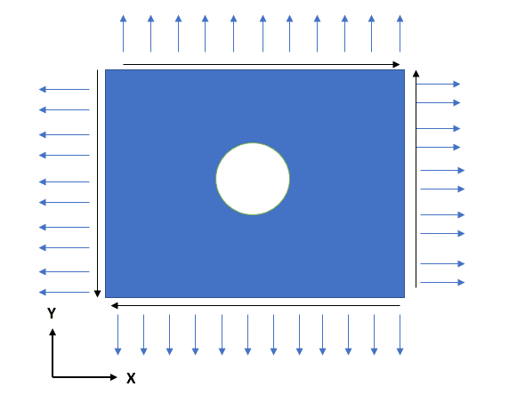
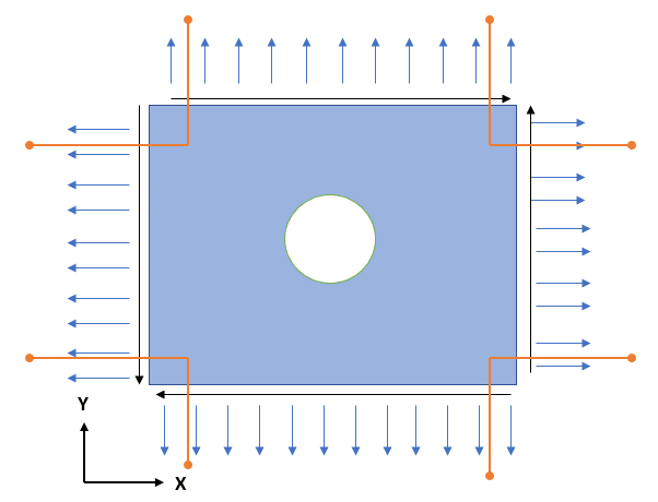
If I want to simulate a plate with biaxial loading with or without shear acting along the edges, what are the different possible boundary conditions which can be specified to capture the deformation pattern accurately (sides of the plate having no curvatures when deformed)?
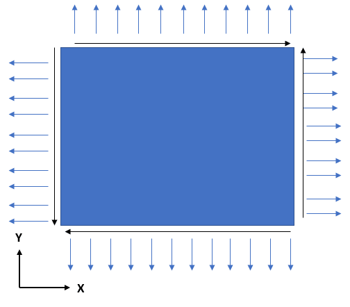
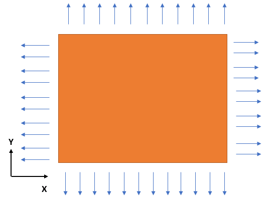
01_nqtbyh.png


02_cqrpaj.png


Thanks...
 
Replies continue below

Recommended for you

Foaces as loads plus two perpendicular symmetry planes to constrain model. And some constraints in Z (perpendicular to screen) direction.
 
^^Thanks for your reply. Applying constraints on symmetric planes might work in the 2nd case but what if I have external shear along with normal stresses?
 
Use diagonal symmetry planes. Make full model and part and compare results. For plates you can constrain all six DOF`s of center node.
 
your 2nd pic looks like principal stresses (possibly from the first pic loads).

sure you can constrain the model to get inplane axial reactions only. Remember rigid body motion (axial inplane reactions as shown react 3 of 6 rigid body freedoms).

I would build a model and load it so shear is not widespread (very uniform loading, uniform reactions); pressure comes to mind.

another day in paradise, or is paradise one day closer ?
 
Karachun,
You may be on to something. Let me try it your suggestion of constraining the centre node of plane in all 6 DOFs.

RB1957, the 2nd pic is just first pic without the shear loads.

Thanks for the replies.
 
"Applying constraints on symmetric planes might work in the 2nd case but what if I have external shear along with normal stresses?"
What are you trying to do/show ? If shear loads are applied, then panel must react them. I thought you were trying to "dumb down" a panel so it sees only inplane normal stresses.

"the 2nd pic is just first pic without the shear loads."
Yes, I understood that ... not knowing what you're trying to do/show, I thought it may help to think of principal stresses.

Please clarify, what are you really trying to do. Are there shear loads or not ? Is the problem constraining the model ? What does the model look like (a single element, a mass of elements making up a square) ?


another day in paradise, or is paradise one day closer ?
 
Do the external loads balance themselves? If that is the case, in theory it should "work" without any constraints. However, because of minor roundoff error, there will be a small imbalance in the numerical solution. If this is not reacted in some manner, then you have RBM.

An approach I have always liked is to just attach a few spring elements (in a few different directions to react X,Y, and Z rotation) to the interior of the plate and then ground the spring elements. These "soft springs" (analogous to bungee cords that prevent RMB) only need to react the minor mathematical imbalance that occurs. You can check the amount of load in the springs, but they should be very small if the external boundary loads are balanced. This approach will prevent RBM without overconstraning the model. I have seen a lot of approaches to this type of problem, but many of them cause overconstraints or constrain a point(s) on the external boundary (removing part of the load), which does not really achieve the best result.

Brian
 
RB,
The 2nd picture was totally not necessary. Sorry about posting it & for the possible confusion. The intent is to understand how to apply Boundary Conditions in FE for a loading situation as shown in picture #1 i.e. Normal stresses along with shear.

The suggestion provided Karachun actually worked. The deformed shape looks alright although I am yet to verify the accuracy of output.

ESPComposites, interesting approach you have suggested. Need to try it.

As usual, thanks for the replies folks.
 
then you can apply whatever constraints you want in order to remove the 6 RBM dof. How you constrain the model only changes the global deflected shape.

if you constrain 1 node in 6 dof then that point is frozen in space and the model deflects around it. If the model has low bending stiffness then this can produce "odd" looking results.

you can constrain 3 nodes in the classic 3-2-1 dof scheme. this defines a plane the model deflects around.

it is unusual to have a model with no natural connection to the rest of the world, but you could have a situation where you know loads and reactions and so you need to restrain the 6 RBM dofs as you like.

you can constrain an entire edge, but with caution as you are over-constraining the model and imposing deflection limitations and stiffness where there may be none.

another day in paradise, or is paradise one day closer ?
 
>>you can constrain 3 nodes in the classic 3-2-1 dof scheme. this defines a plane the model deflects around.
Which 3 nodes in the plate could I constrain?
 
any 3. they define a plane, so pick a convenient plane.

ok, any 3 so long as they define a plane, ie not 3 co-linear nodes !

another day in paradise, or is paradise one day closer ?
 
I apologize for continuing to torment with my questions. If I have a hole in the center of the plate and subjected to 3 external loads (2 normal stresses & 1 shear), where could I constrain to get an accurate deformation with no curvature in the sides.

01_kcpdis.png


ESP, I tried your suggestion of using 1D CLEAS1/2 spring elements to constrain the model, but I am getting RBM error in Nastran. Here is how I set up the analysis.

03_poyzjk.png


The orange lines represent 1D Spring element with low stiffness values and the end orange circles are grounded or fixed in all 6 DOFs. Still getting RBM on some random node near the center of the plate. Not sure what the issue is or how to proceed.
 
For the symmetric plate without a hole, you could probably just constrain a single point in the center. But as you found out, not every model is this convenient. That is where the springs approach can be useful (more general approach).

1. Make sure the Z-direction is constrained for the entire plate.
2. Set the spring stiffness to something "reasonable" like 10,000 to 100,000. It doesn't matter too much since the external loads are self-balancing. You will need to verify that the loads in the springs are relatively small though. You don't want them to pick up a significant amount of load.
3. Make sure the spring inputs to the solver are proper and you are truly getting the 1 and 2 DOF spring stiffness you desire. These are done differently in different codes and can be easy to do incorrectly. I suggest you run some test models with just springs to make sure you are getting the desired I/O (if you are not already comfortable with them).
4. You can add the PARAM, BAILOUT, -1 to the BDF and rerun. Then look at the displacement. This may give you an idea as to where the RBM is coming from and you can then correct it (for example, maybe the springs are not responding how you thought they should or they are still too soft). Also, note that the stress results with this option are *probably* still good (even if you get RBM), but you really need to find out why the RBM occurs and make sure it runs without PARAM, BAILOUT, -1.

I have set up this exact problem (and similar ones) many times and I can guarantee the approach does work. Note that you will still get a "bit" of RBM as the springs move slightly, but nothing that the solver can't handle (provided the spring stiffness is reasonable). But the important thing is that you will have a "pure" result for the stresses and your edge deformation will be as expected.

Brian
 
if you want no curvature along the sides (new problem definition) or no displacement (ie is linear displacement along the edge acceptable ?)

if no displacement then you want an infinitely rigid boundary. Constrain each node normal to the edge and restrain remaining RBM freedoms (3) somewhere/anywhere on the model.

if linear why not mesh refine the boundary to 4 corner nodes ? Else you want an edge member that is infinitely stiff in bending. Or maybe displacement controlled to be a linear function of the corner nodes (an SPC equation).

what happened to the shear along the boundary ?

another day in paradise, or is paradise one day closer ?
 
As someone suggested one can constraint a corner node in DX,DY,DZ, a 2nd corner node in DY, DZ and a 3rd corner node in DZ (assuming the plate is in the XY-Plane).

Another easier way in many software (in Strand7 this exists, and in Nastran very likely), is to use inertial relief to balance an unconstrained model.

This is what is many times used to study buckling of plates/panels in ships and other structure that have complicated loads and where these are impeded/cancelled out by the boundary conditions. In this case inertia relief can be used in an unconstrained plate to generate in plane stresses (which are converted to a geometric stiffness matrix for buckling analysis), then the boundary conditions are changed from free to the appropriate ones (e.g., pinned all around) for the subsequent buckling analysis.

In this case since the forces are self balanced the inertia relief will generate almost zero accelerations/forces in order to balance (so it just helps to resolve the problem with no restraints, which is good).

Hope this helps.
 
I think it depends on whether the OP is looking to solve this specific problem or a general approach (or maybe both). For example, if you were to have an offset hole or multiple holes, you could not rely on symmetry. Constraining the corners in a specific manner will work (you may get some localized stresses that you can disregard), but for general problems in 3D space, the constraint setup is not always intuitive. For any type of structure with self-balancing loads in 3D space, the springs approach will work; the springs only need to stabilize the minor load imbalance in the numerical solution. So it depends on how specific you want to be about the what is considered a solution to this problem. There is more than one answer, each with its own advantages and disadvantages.

Brian
 
You are right.
Software like ANSYS and SW Simulation can automaticaly attach low stiffness springs to constrain model - so called "Weak springs". Also many solvers can use Inertia Relief - add balancing forces to make resultant force zero.
 
In my experience self balancing loads don't remove the requirement to constrain RBM (even pressure in an enclosed volume).

Constraining RBM should not induce stress into the FEM (only if you over-constrain it would I expect to stress stresses due to the constraint). This assumes (obviously) a balanced load set.

another day in paradise, or is paradise one day closer ?
 
Status
Not open for further replies.

Part and Inventory Search

Sponsor