Continue to Site

Eng-Tips is the largest engineering community on the Internet

Intelligent Work Forums for Engineering Professionals

  • Congratulations MintJulep on being selected by the Eng-Tips community for having the most helpful posts in the forums last week. Way to Go!

A Sequel to "Reduction of Transformer Inrush Current" ( thread238-408206)

Status
Not open for further replies.

GroovyGuy

Electrical
May 9, 2016
421
As a sequel to a request that I placed on Eng-Tips (thread238-408206) some 10 months ago; I offer the follow-up:
Original Post
Howdy,
Does anyone have any experience with limiting transformer inrush current. I have several (separate) locations that will experience excessive voltage drop on the incoming Utility feeder. Feeder is 25kV and transformer sizes range from 3MVA up to 12.5MVA. I was thinking of simply using a 25kV reactor, c/w bypass contactor to limit the current to (say) < 2 X IFL. Normal inrush for these transformers in 4.5 to 5.5 x IFL @ 1.0puV.
Voltage-drop w/o these reactors will vary between 25% to over 50%. This level of voltage-drop will not be appreciated by other users on the 25kV feeders.
Thanx


Follow-Up
To date we have had 5 Sites that required a remedy to the issue stated above. Target voltage-drop to be < 6% (per the Utility's request).
Two are now fully commissioned, two will be commissioned in the next few weeks, and one is still in the design stage.
At all Sites the solution was to install one (1) 25kV current-limiting reactor c/w bypass-contactor per Site.
We considered other technologies, such as Point-On-Wave, but decided that the reactor-bypass contactor was the best option with the lowest TIC.

The current-voltage graphs attached to this report were for a site with two transformers rated:
- 5MVA 25kV-4160V
- 2MVA 4160V-600V
Without the reactor, a voltage-drop (at the PoCC with the Utility) was calculated to be > 40%.
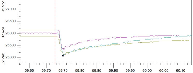
With the reactor in place, the recorded voltage-drop was limited to < 4%.
I will post one more time when the 12.5MVA Site has been commissioned.
Regards
GG
ps If you require any further information, the writer may be contacted at randy@kyebaysystems.com
Overall_RMS_20170317_1_xyuocx.png

Overall_Wave_20170317_1_uplbhw.png

TR922A_Dip_20170317_1_jxrq5k.png

TR922A_DipV_20170317_1_ufkdbb.png


"I have not failed. I've just found 10,000 ways that won't work." Thomas Alva Edison (1847-1931)
 
Replies continue below

Recommended for you

An explanation of what voltages and currents are on the graphs and when the transformers were energized would help. Did you measure both the voltage before the reactor and at the transformer? When were the reactors bypassed? Was any transient analysis performed during the design to predict what the voltage drop would be?
 
Hi GroovyGuy,

I am a bit skeptical of transformer inrush reduction using primary line reactors. Where these reactors paly well with short circuit reduction (where the voltage is already present and decline rapidly to zero on a short circuit), using them on inrush current mitigation may not work well. First of all, unlike short circuit application, your initial voltage condition is zero and then full voltage primary is applied.

The inrush current has a DC component which is proportional to the X/R ratio of the impedance ahead of the transformer primary. Inserting the reactor would further increase the X/R ratio and slows down the primary inrush decay. Furthermore, the inrush also depends on your transformer remanence and voltage period of the applied voltage. For a three phase balanced system, one of your switching will may hit the zero crossing which would amplify your inrush current on one phase.

You add all of them, there will certain unpredictability. I would think you have to measure using a very sensitive device like Dranetz and correlate your measured waveforms of inrush currents in all three phases against voltages measured in all three phases and see whether you hit zero crossing with the transformer at worst case remanence.

regards,
 
Hi jghrist ,
Yes, the system was modeled with EMTP. The expected voltage drop, without the reactor, was calculated to be 42%.
The switching (& timing) of the 25kV circuit-breakers, and the bypass contactor, are PLC controlled. The bypass contactor is only open for 10s during the energization of the (two) transformers.
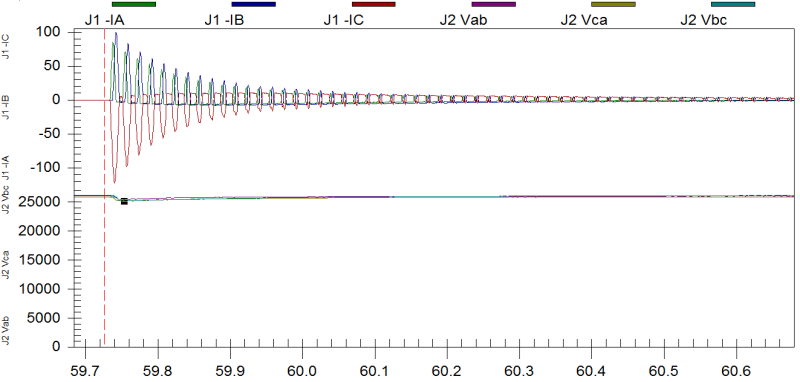
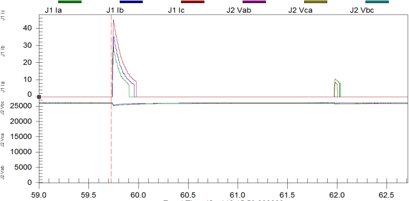
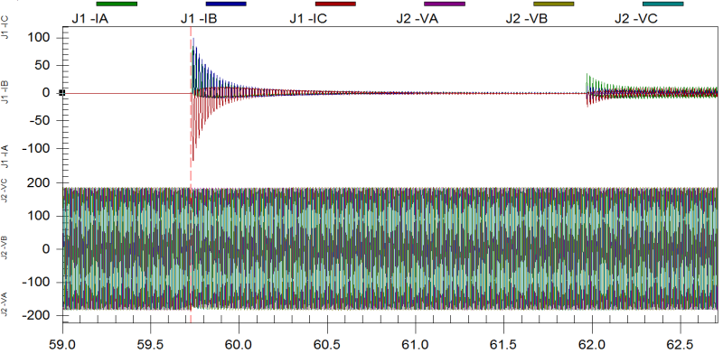
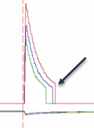
The graphs above, in order from top to bottom show;
1) 5MVA & 2MVA energization: rms Current & Voltage
2) 5MVA & 2MVA energization: instantaneous Current & Voltage
3) 5MVA energization only (ie detail) : instantaneous Current & rms voltage
4) 5MVA energization only (ie detail): rms voltage (detail)

Note:
1) All of the V &I data included on the above graphs are captured with A SEL 751A protective relay. The point of measurement is at the line side of the reactor (ie at the PoCC with the Utility). Unfortunately we did not measure the voltage at the transformer primary. We will capture this data at the next Site to be commissioned.
2) In the above graphs the 5MVA transformer is energized at t= 59.72s and the 2MVA transformer is energized at t = 62s.


"I have not failed. I've just found 10,000 ways that won't work." Thomas Alva Edison (1847-1931)

 
Hi Punisher;
What can I say, the scheme appears to work. As I mentioned above, each Site was modelled in EMTP.
I cannot take credit for concocting this scheme, that really belongs to Toshiba International Corp (TIC) and their medium-voltage drives division. TIC install a current limiting reactor, with bypass contactor, on every medium voltage drive that they produce. This reactor not only reduces inrush current due too magnetizing of the drive's input transformer, but also provides current pre-charge control of the drive's capacitors. I have installed dozens of theses drives (up to 7000hp @ 6900V) at a number of Sites.
By extrapolating the scheme from 6900V to 25kV was not much of a stretch.
We will be gathering additional info at the next 3 Sites. These next Sites include a 7.5MVA, 12.5MVA, and 5MVA transformers on relatively weak systems.
It is also our intention to write a paper, to be published in IEEE. Will keep you up to date on this.
Regards,
GG

"I have not failed. I've just found 10,000 ways that won't work." Thomas Alva Edison (1847-1931)

 
Thanks GroovyGuy for the prompt feedback. Please advise us on any successful development on this endeavor of yours. I will stand corrected on this and this will help us a lot on some limitations that we though existed.
 
Thanks for sharing your results. It looks like the peak inrush was limited to about 1 x IFL and voltage dip limited to about 4%. Is the sudden drop of rms current to zero at 60 & 62.1 sec in the first curve just a calculation quirk of some sort?
 
Hi jghrist,
In the graphs above, the transformer inrush interval was pretty much over is less than 0.3s. This timing was expected as the much lower voltage available at the transformer primary was << 1puV. [Under full-voltage energization (puV =1.0), the inrush current is typically assumed to be over at 0.1s]. The voltage at the transformer primary was calculated to be approx 10% (ie puV =0.10) with most of the avialable voltage dropped across the reactor.

The full-load current rating of the 5MVA transformer is 116A @ 25kV. The peak inrush current (from graph 1) is only 50A. Therefore the inrush current is approx. 40% of the full-load current.
Regards,
GG

"I have not failed. I've just found 10,000 ways that won't work." Thomas Alva Edison (1847-1931)

 
Hi jghrist,
Sorry I did not answer your question wrt the quirk on the graph. I do not know what caused this abnormality to occur. I suspect this has something to do with the accuracy of the CTs and the setup of the SEL relay. I will check this on the next Site to be commissioned.
Regards,
GG

2017-03-27_12-06-50_uahvav.gif


"I have not failed. I've just found 10,000 ways that won't work." Thomas Alva Edison (1847-1931)
 
Below some threshold, metering values read as zero. Depending on what the actual values being plotted are, internal to the relay, they may have crossed into the "call it zero" band. Or, that might be a red herring.
 
1) Series reactors with bypassing switches to reduce inrush currents was mentioned earlier also. It reduces the initial voltage seen by primary winding and hence reduces the inrush current. But why not a resistor instead of reactor? Like the pre insertion resistors used in EHV breakers. It may be cheaper and less complex than a reactor (air cored dry type?) But there are many other options tried for MV breakers.

2) Pre magnetization systems -
3)Another interesting system (reported to be used in ships) is to use a small transformer along with main transformer to pre charge the secondary of main transformer. This small transformer with rated secondary voltage of 90 % of main transformer secondary voltage with current rating of 0.5 % is used to charge the secondary of main transformer. Then the voltage across the primary breaker terminals of main transformer will be negligible to result in any inrush current.
 
Hi prc,
1) Several options were investigated as possible solutions for this problem. The reactor-with-bypass-contactor was chosen for the following reasons;
a) TIC had already successfully demonstrated that this is a workable solution. (ie easy sell to Clients as they all had TIC MV drives at their facilities)
b) Acceptable level of risk
c) Easy to fit into power distribution system at Site
d) Easy to remove from Site should the Utility upgrade their Service (and this equipment is no longer required)
d) Acceptable (if not the lowest) cost

The reactors chosen were air-core type. Resistors were not considered. I am not confident that they would be less expensive than an air-core reactor. Perhaps we will consider this on the next units.

2) Wesemann Pre-magnetizing systems. Interesting, but I am curious if they can do systems up to 25kV. (their website is short on details).

3) This was one of the solutions that was considered, but this solution was considered too costly and complicated for multiple transformer Sites.


"I have not failed. I've just found 10,000 ways that won't work." Thomas Alva Edison (1847-1931)

 
Status
Not open for further replies.

Part and Inventory Search

Sponsor