Continue to Site

Eng-Tips is the largest engineering community on the Internet

Intelligent Work Forums for Engineering Professionals

  • Congratulations waross on being selected by the Eng-Tips community for having the most helpful posts in the forums last week. Way to Go!

A single blown fuse in a 3-phase industrial control panel catches on fire. WHY? 2

Status
Not open for further replies.

bdn2004

Electrical
Jan 27, 2007
792
Inside this panel a single 300A fuse blows up and then catches on fire. The fuses upstream did not blow, neither did the adjacent fuses in the panel. The panel remained energized throughout the whole episode. This feeds an infrared heating system. Any ideas on WHY something like this could happen? And why didn't the fuse just open - instead blowing up ?

The fuse manufacturer was contacted and they said that fuses at low overload currents have trouble opening. They also said it could be there was a solder problem on the fuse or there could be sand fill issues that could cause internal arcing especially in the 600A range of overload.

Any thoughts? Has anyone seen anything like this before? What were your conclusions and things you did to remedy or see that it could not happen again ?
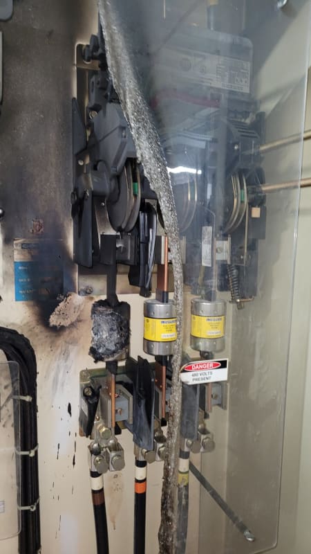
Blown_Fuse_in_a_panel_ja3ljk.jpg
 
Replies continue below

Recommended for you

It looks more like an arc formed on the outside of the fuse, bypassing it, and melted the fuse housing. With less current through the fuse and the plasma carrying the current, there would be no ability for the fuse to blow. The current would be limited by the resistance of the heaters. Is there any sign of a mouse that might have completed the circuit for an instant, initiating this?
 
Some fuses have a problem with low overloads that heat the sand and make it pack, so that when it needs to blow it will not blow correctly. This should be in the manufactures data.
One option is to replace the fuses from time to time.
Another is to use a different type of fuse that does not have this problem.

Did someone assume that one fuse is the same as another when recommending for this application?
 
A mouse....that's a new thought. I know at my own house on the outside wiring under my deck....it seems mice for some reason like chewing on the UG electrical wiring that's exposed. The insulation on that phase of cable is melted through. There is also copper splatter in the panel indicating this thing got really hot.

I don't know why that particular fuse was specified for these panels. I'm not sure they would have put a lot of thought into it other than giving it the over-current protection required for the panel. But I might be wrong.
 
Full disclosure, my background is with bigger stuff, not this low voltage stuff.
 
Cranky108,

Actually I think your concern is one worth suggesting to the Owner, so thanks. As you know they make all sorts of fuses for different applications - perhaps that's not the right fuse for this one and it needs to be looked into further. No one was working on this at the time - it's just a malfunction.
 
Never assume:
You have assumed that the fuse blew, but you have not given any indication of a fault of overload downstream.
Look at your connections.
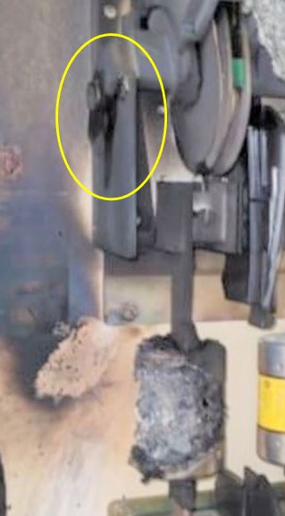
The blade below the fuse body is still clean.
The upper blade shows heat damage on its entire length.
You have a may have loose connection at the disconnect switch.
That can generate a lot of heat.
Heat conducted by the copper could melt the fuse links at less than rated current.
With the internal link melting slowly, it could have developed a small arc despite the sand packing.
That would only get worse.
I won't speculate as to the sequence of the actual deterioration and breakdown.
I do suggest that there is a high probability that the damage started as a result of a poor contact and not from overload.

--------------------
Ohm's law
Not just a good idea;
It's the LAW!
 
This looks similar to a situation we had a few years ago on a very similar fused disconnect in a VFD panel. In that case, the fuse did blow and the drive was very close to a large, lightly loaded dry type transformer. When it blew, the voltage surge (caused by the transformer inductive kick) caused an arc on the energized line side. In that case it went phase-to-phase, not phase-to-ground. It does look like this arced but it's surprising it did not migrate over to the other line.
 
waross' summary is the same as what mine would have been, poor contact rather than high current.
It doesn't take much resistance to dissipate a significant amount of heat and end up in this situation.

That said, it does appear that there may have been some sort of arc or contact on the back to the left of the fuse.

EDMS Australia
 
Dear Mr. bdn2004 (Electrical)(OP)8 Nov 21 14:51
"... 1) Inside this panel a single 300A fuse blows up and then catches on fire. 2) The fuses upstream did not blow, neither did the adjacent fuses in the panel. The panel remained energized throughout the whole episode. ... 3)... why like this could happen? And why didn't the fuse just open - instead blowing up ?
4)... The fuse manufacturer was contacted and they said that fuses at low overload currents have trouble opening. They also said it could be there was a solder problem on the fuse or there could be sand fill issues that could cause internal arcing especially in the 600A range of overload..."

A. Observation from the picture:
a) fuse top blade sign of over-heating, bottom plate is clean. [Probably due to loose connection ?]
b) fuse body including the end caps are badly over-heated. [Probably (the body) is of [combustible material] (e.g. paper) instead of ceramic (e.g. china). Replace it with a ceramic body if available. Most important is to ensure low contact resistance].
c) likely cause is over-heating; conducted from the top blade down to the fuse body. [ it is unlikely due to over-current. It should blow if > 300A or >> 300A; without over-heating the body. It could be it catch fire then heat up the fuse element, instead of over-current that melts the fuss element that caused the fire].
B. Suggestion: 1) ensure low contact resistance. 2) Replace it with a type body of ceramic (china) instead of paper.
Che Kuan Yau (Singapore)
 
Adding to Bill long-term overheat scenario the infra-red heating system could provide a lagging pf that helps establish and maintain an arc.

Keith Cress
kcress -
 
I am not sure what this is ?
If it is a cause or a consequent.
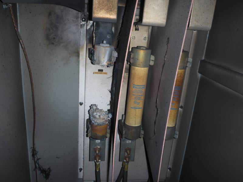
It looks like the isolation between the what I assume is the disconnect breaker have failed.

0_s0hq5t.jpg


Best Regards A

“Logic will get you from A to Z; imagination will get you everywhere.“
Albert Einstein
 
Itsmoked,

Why does a lagging pf help sustain an arc? In another recent post I had on power monitoring...it's interesting in the data we collected on the input of a 300 Hp dc drive - the power factor was low - like 0.65 as an average as compared to a similar ac application where the pf on that drive was like 0.85 as an average. Is the infrared heater like the dc drive ?
 
Why does a lagging pf help sustain an arc?
Zero crossing.
Arcs are conducted through plasma which is very hot.
When the sign wave crosses zero the arc stops for a time best measured in micro seconds.
During the zero crossing the plasma cools slightly and as the voltage and current build from zero the arc may re-establish.
With a non-unity power factor the current and voltage zero crossings are not simultaneous and the momentary arc interruptions are shorter.
As a result the arc is more difficult to extinguish eliminate.
Straight resistive heating will be at unity power factor.
I suspect that Keith has worked on more sophisticated infrared heating systems that incorporate transformers or other devices that draw reactive current.

--------------------
Ohm's law
Not just a good idea;
It's the LAW!
 
How are folks identify the long term heat damage on the upper blade? Both the upper blade and the wall appear to be covered in similar black soot.
 
I agree with bacon. To me it appears that there was a sustained arc inside the fuse, which blew it open and burned it up, causing the soot.
 
That may be soot on the upper blade, but the colour of severe and rapid heat corrosion on copper is very black.
On site the difference will be readily apparent from the texture, but it is difficult to tell the difference in the photo.
I am not ready to argue strongly either way.

--------------------
Ohm's law
Not just a good idea;
It's the LAW!
 
Are these fuses current limiting type (CL)?
I believe that this fuse is there for short circuit protection and not for any overload protection downstream.
So if there had been a fault downstream and there was not enough fault current to melt the fuse (specially CL fuses)
or in other words there was not enough fault current to pass its minimum melting current, then the fault current
will go through the fuse continuously but no melting occurs. Finally the fuse will explode due to its own heat generated.
This happens when we install fuses for sc protection where there is no enough fault current in the systems to achieve even its minimum melting current.
UPS distribution is a very typical example.
What is your grounding method?
I am sure that there had been a high resistance ground fault downstream.
You may have to check the integrity of your ground return path.
 
A look at the fuse after removing it from the clip would give some indication if it was a loose connection at the clip or not.

I can't recall seeing a low voltage fuse do that but it could be possible. The fuse could have a current operating range where it runs too hot to dissipate the heat but there is too little current to properly open the links inside.

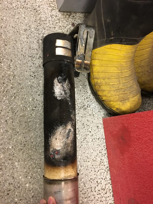
I've seen a few cases of this with 5kV class fuses. This one appeared to be a bad or overloaded fuse.

IMG_0667_gigary.jpg


This was likely overloaded and it must have sustained an arc for a while for the body to disappear. I'm not positive but I think it flashed over to ground at the top bar where it bends.

P1010355_ttzqtn.jpg
 
Status
Not open for further replies.

Part and Inventory Search

Sponsor