Hello everyone, hope you're all doing well in this current situation, as well as your loved ones! Hope you can help me as i'm really stuck on this one.
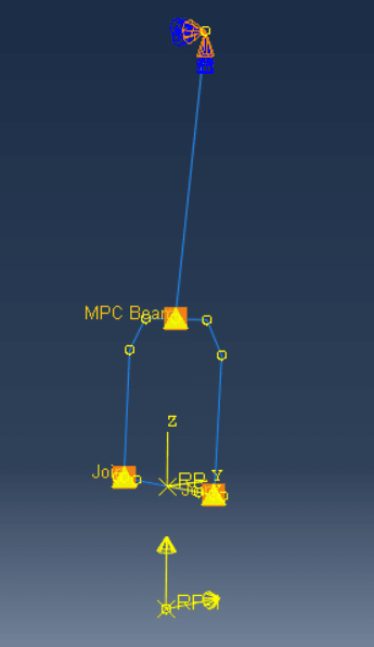
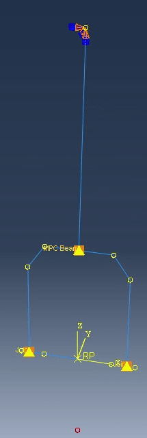
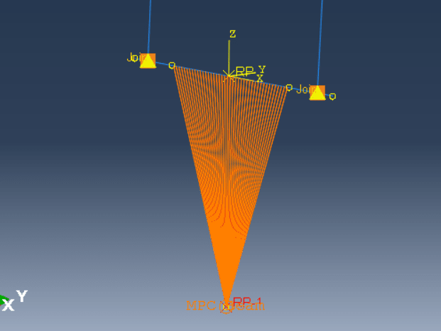
Im applying a vertical and horizontal load on an ABAQUS 2D beam assembly as shown. I need it to be at the red point that is under the model as can be seen in one of the images, and want that point to transfer the load applied, including its moments, to the horizontal beam untop of it. I’ve done that by using an MPC constraint at that point that I specified as a Reference Point and applied two loads on the Reference Point that I have defined, as you can see in the attached image. I keep getting this error when running the job: “Too many attempts made for this increment”. I have tried to reduce the initial step time and increase the mesh, to no avail. Is there anything i’m missing here? the loads I applied were concentrated forces on the RP-1. Should I be placing boundary conditions on the axle to which the RP is constrained to? (which doesnt make sense in my opinion). Do note that when I applied loads on the axle right away as a line load, the job ran perfectly.
P.s. what im working on is a landing gear assembly simplification for the DHC-6 nose landing gear. The lower horizontal beam is the wheel axle, and RP-1 is the point of contact of the wheel with the landing strip. The two forces I applied are the drag force and vertical force on impact. I'm using a general static step.


