stonehentsch
Civil/Environmental
Dear forum users,
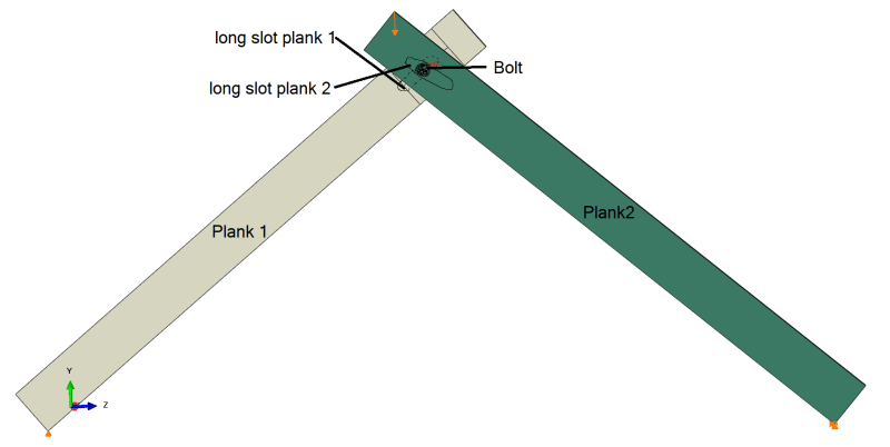
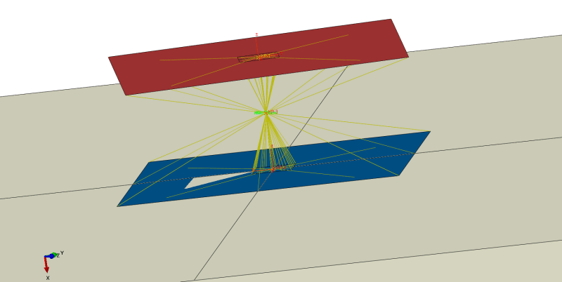
My model as you can see in the attachment file consists of 2 planks, each with a long slot along the length. The two planks are held together by a bolt which can slide along each of the long slot. I want to simulate that connection by connecting a reference point (CP1) positioned on plank 1 with a shell surface (shell1) via kinematik coupling constraints. This means the shell surface is coupled to the movements of the reference point (KP1), except movements in the direction of the x-axis of the local coordinate system placed on plank 1(u1 in the attachement file). This simulates the allowed movement of the bolt along the long slot. Then this shell is coupled to another reference point (CP3) via MPC-Pin. This allows the bolt to rotate aswell. The bolt in this scenario is referece point CP3. Then this referencepoint CP3 is coupled with another shell (Shell2), again via MPC-PIN. This second shell is coupled with a reference point(CP2) via kinematic coupling constraints. This shell (shell2) is again only allowed to move along the x axis of the local coordinate system placed on plank 2.
Is this a reasonable approach to the problem? i tried MPC SLIDER which didnt work out, since u need 2 MPC SLIDER working in oposite directions canceling all DOFS. Which shell type should i use for this, since abaqus aborts saying reference point 3 CP3 is missing a degree of freedome.


