1. In ABAQUS, when tieing a face and a node set, if the slave face is composed of a node set, is it only at the node's contact position with the face that there will be constraints? Will slave nodes and slave nodes bind to each other? Will the part of the slave node that is not in contact with the master face have an effect on the master face?
2. When we output the shell unit result, how can the visualization interface call out the data of 5 integration points along the thickness direction? Which integration point is the most accurate one to refer to?
3. Is tie constrain (without constrained rotation) consistent with MPC-PIN?
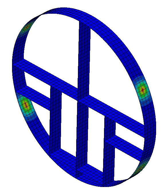
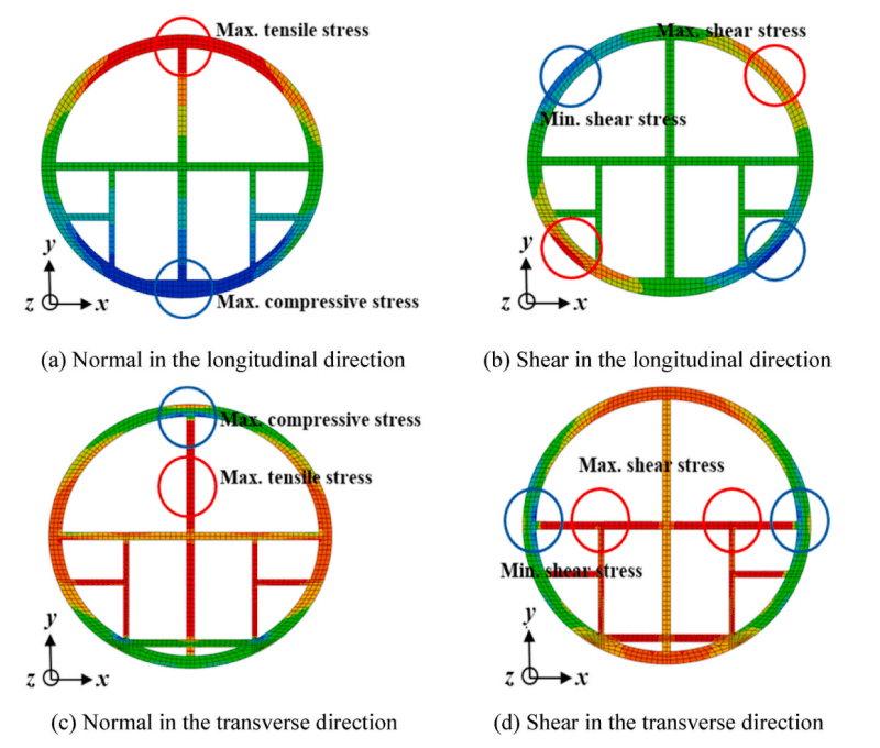
4. As shown in the left figure below, this model shows a significant stress concentration when only subjected to upward gravity. Is there any way to resolve this? Tried the external re-build member approach, but that doesn't solve it either. The picture on the right is an article and I would like to ask why this phenomenon does not occur in the article.
2. When we output the shell unit result, how can the visualization interface call out the data of 5 integration points along the thickness direction? Which integration point is the most accurate one to refer to?
3. Is tie constrain (without constrained rotation) consistent with MPC-PIN?
4. As shown in the left figure below, this model shows a significant stress concentration when only subjected to upward gravity. Is there any way to resolve this? Tried the external re-build member approach, but that doesn't solve it either. The picture on the right is an article and I would like to ask why this phenomenon does not occur in the article.