Continue to Site

Eng-Tips is the largest engineering community on the Internet

Intelligent Work Forums for Engineering Professionals

  • Congratulations IDS on being selected by the Eng-Tips community for having the most helpful posts in the forums last week. Way to Go!

Abaqus ductile damage parameters 1

Status
Not open for further replies.

O. Beckmann

Civil/Environmental
Jul 15, 2020
5
Hello,
I was wondering if anybody would be willing to share their input data for ductile and shear damage initiation (tabulated data for strain rate, stress triaxiality and eq. plastic strain at initiation for ductile damage and strain rate, shear stress ratio and eq. plastic strain at initiation as well as ks-factor for shear damage) and damage evolution for mild/constructional steel (preferrably S355, but any data to start with is welcome).

I understand that the data needs to be obtained from / calibrated to specific material tests like dog bone tensile tests or special triaxiality tests. Unfortunately, I do not have such test results (yet). I do have tensile test results (sigma-epsilon curves) which I could use for some adjustments to the simulation damage parameters, but I am sure that such simple tensile tests are inadequate to try to prepare a full set of input data for the damage model in ABAQUS.

The purpose of this approach is to prepare an initial simulation of a structural steel test setup in order to have an estimate of the expected outcome. Before carrying out the actual bigger scale test, I could do some more material tests to verify or adjust the material data.

I hope that somebody can help out and is willing to share their work as a starting point.

Best regards and greetings from Germany,
Oliver Beckmann
 
Replies continue below

Recommended for you

Such data can be found in scientific articles. For example "A Numerical Study of the Behaviour and Failure Modes of Axially Compressed Steel Columns Subjected to Transverse Impact" by H. Al Thairy and Y.C. Wang.
 
Hi FEA way,
Thanks for this very helpful hint. I have not found any article including shear damage model parameters before...
This is a good starting point.
 
Hello!
I can suggest you to use the Abaqus Examples-1 problems, 2.1.16 PROGRESSIVE FAILURE ANALYSIS OF THIN-WALL ALUMINUM EXTRUSION
UNDER QUASI-STATIC AND DYNAMIC LOADS has several material damage models parameters.
 
Hi,
Yes, I am aware of that Example. But this deals with aluminum material which has significantly different material parameters.
Especially when it comes to shear failure model, I do not have any complete failure parameter set for steel (e.g. S355). The article mentioned above by FEA_way does contain some strain and failure parameter data, but does not give e.g. the Ks-value for the shear damage model which is supposed to be a material constant given as 0,3 for aluminum in that example. I have not found any hint about this parameter for mild steel. Unfortunately, I do not have any test results to verify or check that shear failure model. That is why I was hoping to find some kind of suitable data.
I found a master thesis by Henning Levanger about "Simulating ductile fracture in steel using finite element method: Comparison of two models for describing local instability due to ductile fracture". Although the material models are somewhat ill-posed to fit the verification approach of the thesis, this was a good basis for me. But it deals only with the ductile damage model.

One related specific question about the behaviour of the ductile failure model that I have come across during my verification approach:
May be somebody has an explanation for it...or does have a better understanding of the internal Abaqus deifnitions.
What is really meant by the equivalent plastic displacement (u_f^pl), which, according to Abaqus manual, is defined to be the plastic strain at failure multiplied with the characteristic length of the element (u_f^pl = Eps_f^pl * L) and how does this influence the result? May be I did not understand the definition of the characteristic length correctly...?

So far, I approached its behaviour by a simulation of a simple round steel tensile tie rod pulled to failure - see attached pdf to explain the situation. I have tried to match a test result by first doing an analytical approach to find a suitable value for it. With a true failure strain of e.g. 0.29 from the test result and an element size of ~2mm (3D-element with linear interpolation, so L should be sqrt(3)*2mm=3,5mm), the displacement at failure would be u_f^pl=0,001015 m. After running a simulation, I found that the damage initialization (SDEG>0) started as defined at a plastic strain of 0,15. But after that, I could not find any correlation between the defined failure criteria and the resulting degradation values and strains in the elements. I defined a tabular degradation with a shallow slope in the beginning and a steep slope at the end to be able to see the point of sudden change of degradation. I enxtended the plastic material data according to a true stress strain hardening equation in the form Sigma_T=K*Eps_T^n up to a true strain of around 2, so that I did not run into the end of the plastic material definition in the damage failure zone (I encountered this problem in my early simulations where I could not explain a change of slope in the plots during the damage evolution when I applied a linear degradation...). What I could not explain is that the measured degradation and strains developed differently in different elements and the degradation slope change started at different strain levels. How can this be explained? Is the characteristic length a variable changing with the deformation of the elements?
When I increased the value for u_f^pl with the same degradation value, I expected to "delay" the failure - to have a bigger elongation at a similar reduction of the reaction force. But it turned out to result in a reduced reaction force with no significant increase of elongation...

May be someone can bring light into that dark ...?

Thanks,
Oliver
 
 https://files.engineering.com/getfile.aspx?folder=f2bf0709-d7a4-428e-83c2-52d3d0ed2f8b&file=Tie-rod-damage-behaviour.pdf
May be one other simple question:
I tried to combine both ductile and shear damage models once. The damage initiation variables DUCTCRT and SHEARCRT always showed the same value. Is it so that these variables show the maximum level of both models (since the failure/degradation rule is defined to be the maximum of both models as a standard)? Is it somehow possible to find out the damage initiation level (and also the damage evolution level) of each of the two models?

BR,
Oliver
 
Hi again.
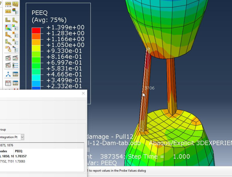
Another point - why have these elements not failed - PEEQ of 1.73 meaning the elements are 5.6-times longer than originally (the following view is NOT scaled!).
Damage_wvhi73.jpg


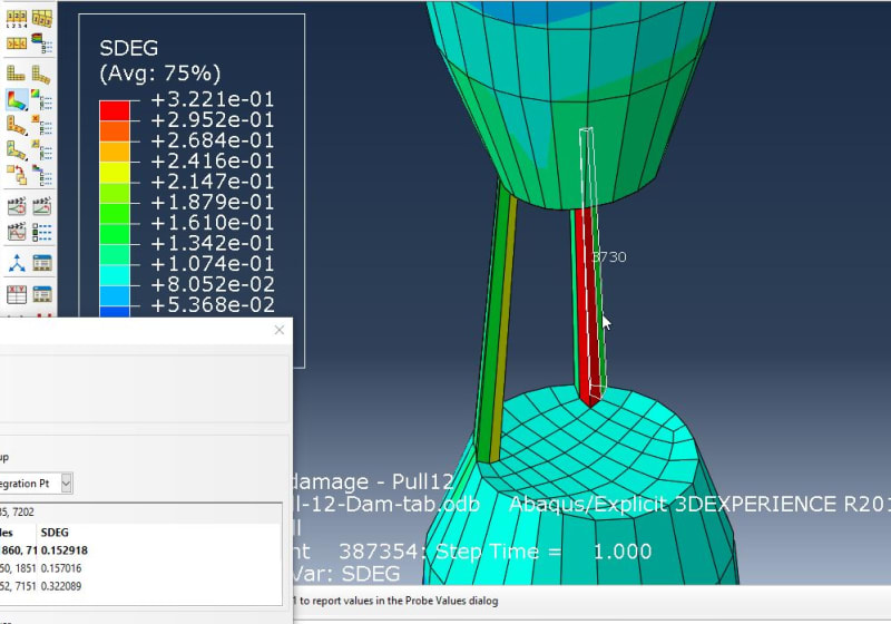
But the degradation is only between 0.15 and 0.32 - how does this happen?
Damage2_whxgsv.jpg


Triax value of these elements is between 1 and 2.1.
ER (change rate of strain) is as high as 6.6 .
But these values are well covered by damage initiation criteria.
Ductile damage initiation
0.15 -0.3 0.1
0.15 5 0.1
0.15 -0.3 300
0.15 5 300

How does this fit together?? I have no idea why these elements are so slightly damaged.
 
Status
Not open for further replies.

Part and Inventory Search

Sponsor