Continue to Site

Eng-Tips is the largest engineering community on the Internet

Intelligent Work Forums for Engineering Professionals

  • Congratulations MintJulep on being selected by the Eng-Tips community for having the most helpful posts in the forums last week. Way to Go!

ABAQUS/Explicit: Guideline on Hourglass control energy limit? 1

Status
Not open for further replies.

ShadowWarrior

Civil/Environmental
Aug 21, 2006
171
What is the guideline on Hourglass control energy limit?

Somewhere its suggested to keep it less than 1-2% of the Internal energy; somewhere else its less than 5% of Strain energy and somewhere else its said to be less than 10% of Total energy.

We need a definite guideline on this, a fixed parameter and a fixed value.
 
Replies continue below

Recommended for you

Here is a non-answer:

This is a tough one because I think this is where prior experience and skill come in to play; some may call it voo-doo but I want to think of it as art. As long as the numerical juice (non-physical energies: hourglass, stabilization, .. ) makes a tiny fraction of the physical energies in the simulation, then I feel pretty good. So, depending on the problem, I may rely on high school/early undergraduate level physics, experience (my own, others', published work, etc.), and intuition for this one.

*********************************************************
Are you new to this forum? If so, please read these FAQs:

 
there are some old abaqus training notes online that state the following:

"Verify that the artificial energy used to control hourglassing is small (<1%) relative to the internal energy. Use the energy output quantities ALLAE and ALLIE to verify this. The exception to this rule is the case of elastic bending with a coarse mesh when enhanced hourglass control is used."

Generally I would agree with the statement above though - if you have to introduce artificial energy in an analysis, make sure its a small fraction of the physical energies.
 
In my simulation , I'm having >5% of Internal energy. Not sure how I should defend this in journal writing...

Until now I have used C3D8I to get rid of all types of element related shortcomings, but it has 8 times the number of integration points than C3D8R and it is taking ages to complete a simulation run (11 days to be precise). Using C3D8R will surely help me actually get something done other than staring at the screen for eternity.
 
Assuming you have run your analysis with C3D8I and C3D8R can you compare the results - is there any notable difference in the variables of interest? How do they compare to actual experimental measurements or data reported in the literature. Its up to you to defend/validate your model. If you can reasonably justify your assumptions and demonstrate good validation against real measurements I don't think you will have a problem publishing your work.
 
I'm interested in load-displacement relationship. Even if they match well between experiment and simulation, should I point out >5% internal energy or just suppress it in paper?
 
Run one case with C3D8I/C3D8 elements and compare the force-displacement with that produced using C3D8R w/ default hourglass control. If they are identical, I would continue using C3D8R elements for the rest of your cases. If not, consider C3D8R w/ non-default hourglass control.

In your paper you can state the following:

"The energies were monitored throughout the duration of the analysis and ALLAE was found to be X% of ALLIE which is above the recommended threshold of 1%. However when an identical analysis was completed using C3D8I/C3D8 elements, no difference was observed in the force-displacement response."

In my own experience in my field, this level of detail is rarely included in journal articles.
 
Thanks Dave, I'm actually doing that right now.

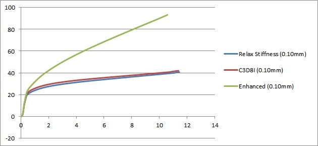
The Enhanced hourglass control is said to be winner allover, but I often find Relax stiffness to produce better result. I think Relax stiffness is the default for C3D8I/C3D8/C3D8R in Abaqus as well?
 
Load-displacement: (C3D8I vs C3D8R)

1_vb8nz1.jpg


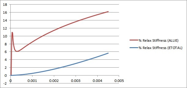
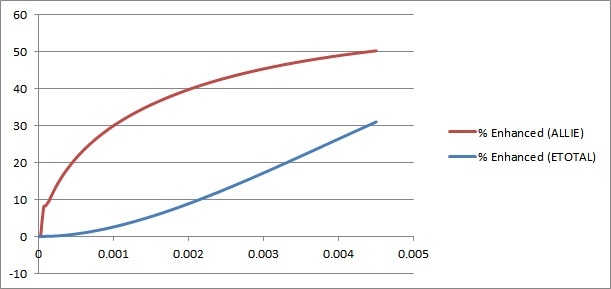
Hourglass control for C3D8R:

2_wighse.jpg
3_kknmej.jpg


So it seems that Relax stiffness produces better result than Enhanced hourglass control. Any comments?? Also, is Relax stiffness the default hourglass control for C3D8R element?
 
I'm surprised you see such a massive change in your load-displacement results. But then I don't know anything about your analysis/model. Enhanced hourglass controls are generally beneficial, but can yield an overly stiff response in problems displaying plastic yielding under bending. That's straight from the manual.

Have you compared ALLAE and ALLIE for both analyses?
 
@Dave442 - Yes, look at the bottom two images.

For left image -
% Relax Stiffness (ALLIE) = (ALLAE/ALLIE)*100%
% Relax Stiffness (ETOTAL) = (ALLAE/ETOTAL)*100%

Same calculation for the right image (% Enhanced).

Do you think ALLAE values are too much??
 
Sorry, I didnt realize what you had plotted. The ALLAE/ALLIE % seems high for both hourglass control options. Can you share the details of your analysis? I guess its good that you don't see much difference in the load-displacement response for C3D8I and C3D8R w/relaxed stiffness option. Is it possible to compare to physical measurements?
 
@Dave442 - Its a drop impact test analysis, here is a picture of the model -
It will not match with experimental results in Continuum scale, needs multiscale analysis as the structure is at micron scale actually. :)

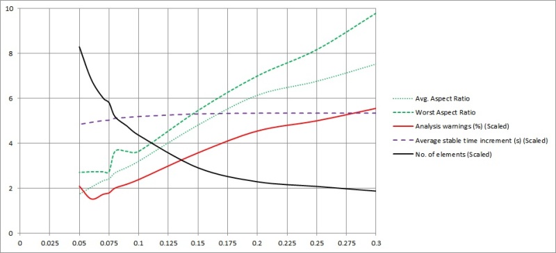
So for now my target is to use C3D8R elements instead of C3D8I, but to keep the mesh coarser and get the same load-displacement result. I selected a nominal element size of 0.075mm based on the below meshing parametric study -

Untitled_fmeize.jpg


Note that some parameters have been scaled (by multiplying with a fractional number) to fit the range between 0 to 10. Do you have any comment regarding this novel idea on element size selection? :)


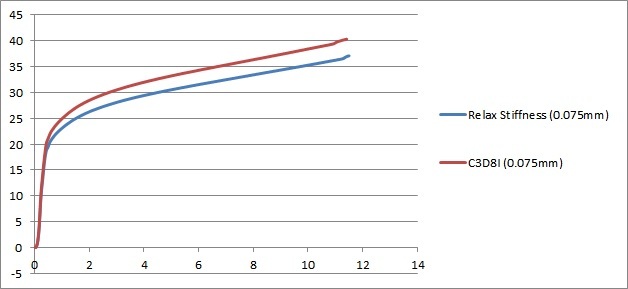
Now with this 0.075mm element size:

Load-displacement: (C3D8I vs C3D8R)

Untitled_dniuwh.jpg


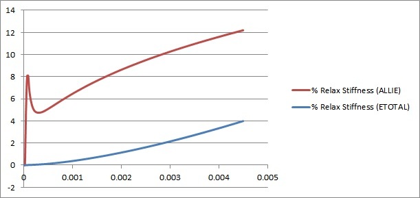
Hourglass control for C3D8R:

Untitled_wa7pcv.jpg
 
Have you evaluated the effect of mesh refinement on the ALLIE/ALLAE %? Your mesh looks coarse and refinement should reduce hourglassing:

"A good way to reduce hourglassing is to refine your mesh"

Also, it seems stiffness-based controls are prefereable for drop test analyses:

"As a general rule, stiffness-based algorithms are more effective for lower energy simulations like drop tests"

Finally, in your first chart, you do not include the variation of any field output or variable of interest? So its impossible to say whether your mesh is converged at 0.075mm?
 
From your first link - "The point is to confirm that the nonphysical HG energy is small relative to peak internal energy for each part (<10% as a rule-of-thumb)." This is good news as I'm seeing ~12%. The current model has 380,000 elements and its taking 3 days (still running) to finish a run. I'm not sure if I can afford to refine the model anymore as it will increase the computational cost dramatically.

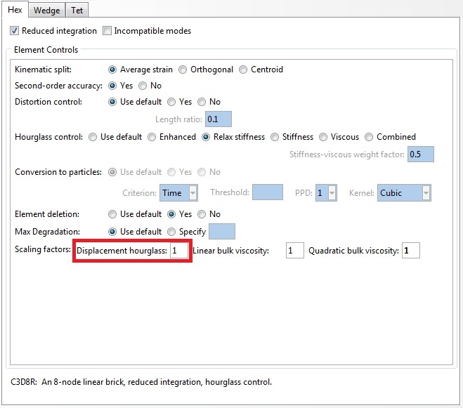
One thing to note that, Whatever hourglassing I'm using, the displacement hourglass scaling factor is set to 1. Should I change it?

PrtScr_capture_3_sm7lww.jpg
 
Your mesh looks a bit coarse if they are C3D8R's but its up to you to establish convergence.

Your model looks like one repeating structure that is mirrored/patterned multiple times. Maybe you could run your sensitivity analyses on this small section alone? Just to quickly determine the effect of mesh refinement, element type and controls on your results?

Also, have you checked the critical element in your mesh? Sometimes when copying/merging instances you can make small sliver elements which are almost impossible to detect by eye. In an explicit analysis, these sliver elements will torpedo your stable time increment.

Just some suggestions, not sure about the displacement scaling factor - never alter it myself.
 
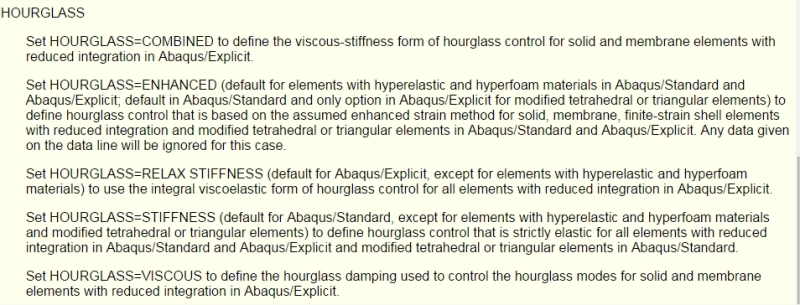
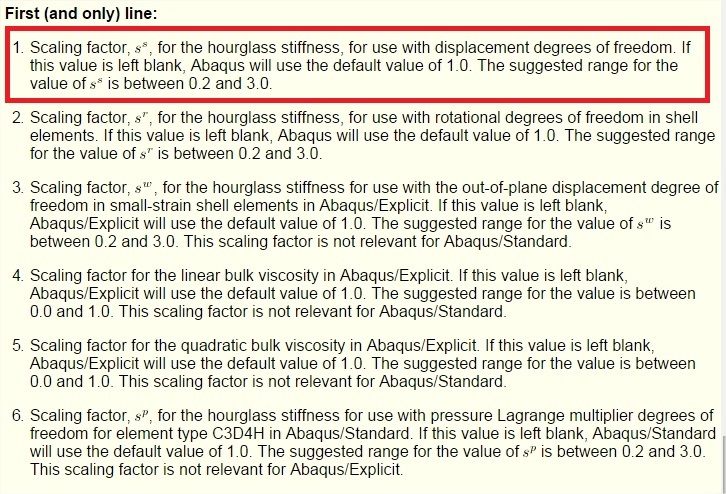
@Dave442 - From Abaqus docs on stiffness scaling factor -
PrtScr_capture_5_sedjv2.jpg


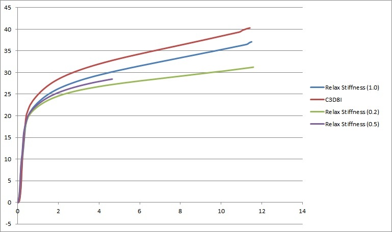
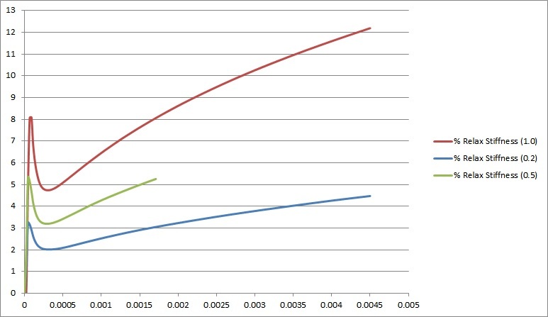
So I varied the scaling factor and the results are below. Note that scaling factor less than 1 (default) causes softening effect, I imagine value greater than 1 will cause hardening effect but the hourglass control energy will increase too. I terminated the analysis for scaling factor 0.5 since its showing the same trend in both load-displacement and Hourglass control graph.

Load-displacement: (0.075mm element size)

10_xlve8y.jpg


Hourglass control energy for C3D8R: (0.075mm element size)

11_d2poes.jpg


Should I try other Hourglass control methods? So far I have tried Enhanced and Default = Relax stiffness.
 
I can't say? Can you compare your load-displacement results to experimental measurements to determine the best approach?

(This is assuming all your other modelling assumptions are justified)
 
@Dave442 - Basically I'm trying to verify C3D8R model against C3D8I element model. I have refined the mesh further, below is the load-displacement curve for finer and coarser mesh, it is evident that finer mesh does not have much impact. Stiffness scaling factor = 1 is used in all cases. Note that C3D8I gives stiffer result, which is logical due to "volume locking" of fully integrated elements.

Load-displacement:

20_lfsoj6.jpg


Hourglass control energy for C3D8R:

21_juied1.jpg


Any comments on the above??
 
Status
Not open for further replies.

Part and Inventory Search

Sponsor