Hello,
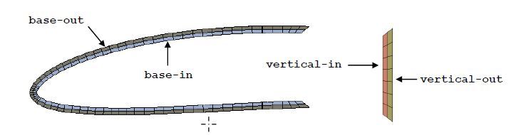
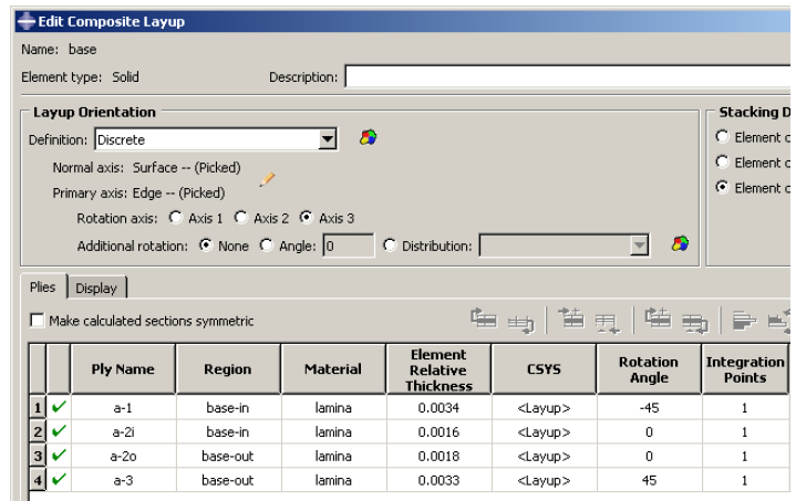
I am modelling a composite bicycle rim using continuum shell elements. I am a little confused with how ABAQUS distributes ply properties to elements through the shell. What if I have for example 3 elements through the thickness, but the stacking sequence uses 9 plies?
I found an ABAQUS tutorial which creates sets for each element layer through the thickness and assigns an appropriate number of plies. So for my example case that would be 3 sets each with 3 plies.
Does anybody know if this approach can be avoided? When the geometry is complex and meshes are fine, selecting individual element layers is very impractical. Will ABAQUS distribute the ply propperties among the elements itself if you just assign the stacking sequence to the whole section?
-Thanks!
Chris