lambosan16
Student
Hello.
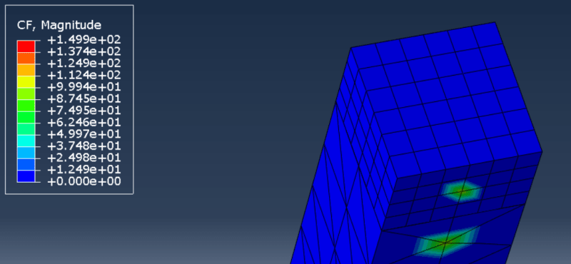
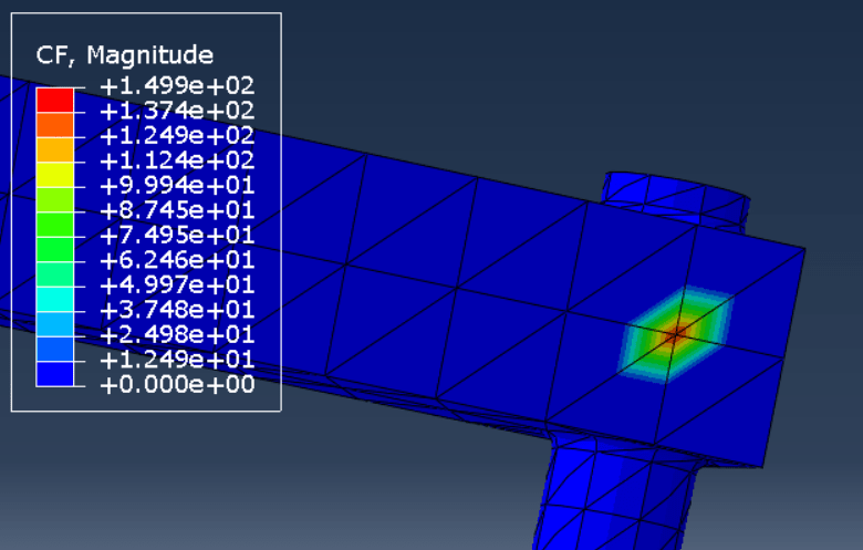
I am kinda new in these topics of FEA and using Abaqus. I am trying to apply two concentrated loads to a single body by using reference points. I relate both reference points to the model by using Rigid Body constraints, and selecting the surface at which the point loads should be applied. Multiple messages of the following error appear: "NODE ### INSTANCE PART-1-1 HAS TWO RIGID BODY REFERENCE NODES 3 (ASSEMBLY) AND 1 (ASSEMBLY). NODES SPECIFIED IN A PIN NSET OR TIE NSET OR NODES WHICH ARE PART OF AN ELEMENT SPECIFIED IN AN ELSET MAY HAVE ONLY ONE RIGID BODY REFERENCE NODE". I tried creating a partition of the surface, thus relating the reference points to different surfaces, but it did not work either (same messages appeared, but with different nodes). What solution should I try?
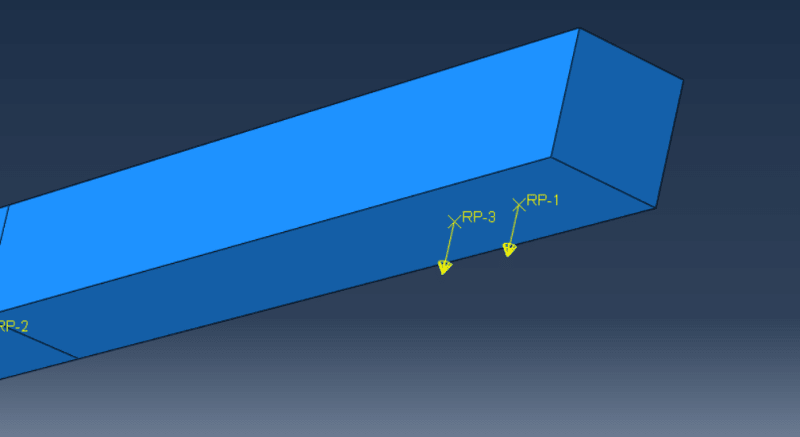
I am kinda new in these topics of FEA and using Abaqus. I am trying to apply two concentrated loads to a single body by using reference points. I relate both reference points to the model by using Rigid Body constraints, and selecting the surface at which the point loads should be applied. Multiple messages of the following error appear: "NODE ### INSTANCE PART-1-1 HAS TWO RIGID BODY REFERENCE NODES 3 (ASSEMBLY) AND 1 (ASSEMBLY). NODES SPECIFIED IN A PIN NSET OR TIE NSET OR NODES WHICH ARE PART OF AN ELEMENT SPECIFIED IN AN ELSET MAY HAVE ONLY ONE RIGID BODY REFERENCE NODE". I tried creating a partition of the surface, thus relating the reference points to different surfaces, but it did not work either (same messages appeared, but with different nodes). What solution should I try?
![[dazed]](/data/assets/smilies/dazed.gif "[dazed] [dazed]") ). If someone manages to do it by only using reference point, and excluding the nodes (as noted by the comment above), please post how you did it for future reference.
). If someone manages to do it by only using reference point, and excluding the nodes (as noted by the comment above), please post how you did it for future reference.