Continue to Site

Eng-Tips is the largest engineering community on the Internet

Intelligent Work Forums for Engineering Professionals

  • Congratulations GregLocock on being selected by the Eng-Tips community for having the most helpful posts in the forums last week. Way to Go!

Abaqus - Microforming Process

Status
Not open for further replies.

BMBr

Mechanical
Dec 29, 2022
4
Hi everyone,
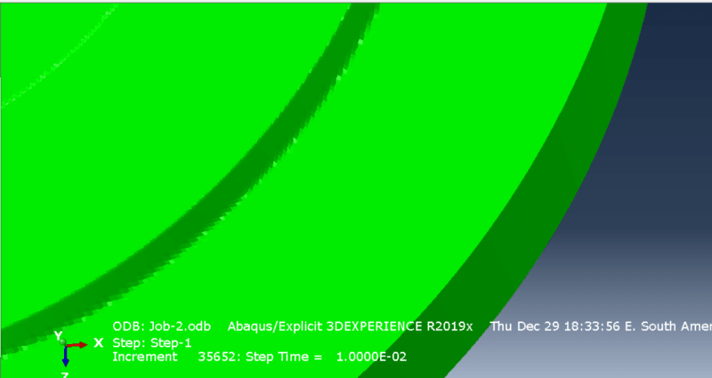
I'm trying to simulate a coining process with microgeometry with 0.2mm in the width relief, and I noticed some poor aspect in the final form of the coin. The Figure 1 shows a quarter of the coin and a bad appearance in the contour of the relief with bright spots.
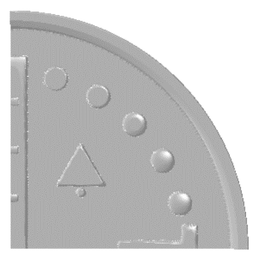
Figure_1_pl7hda.png


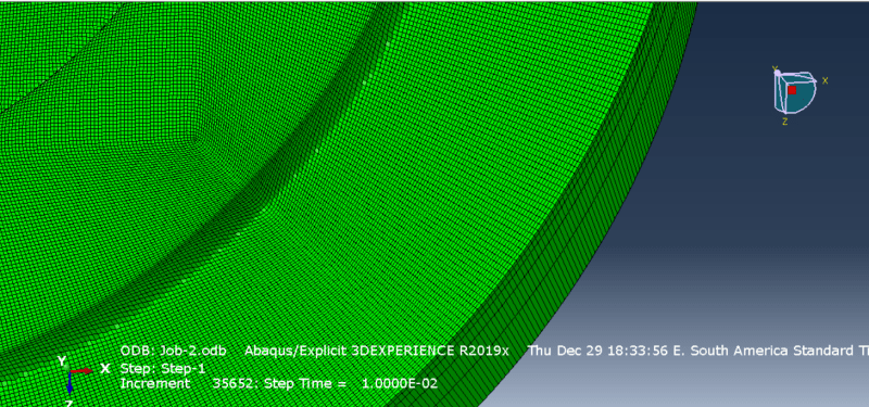
The figure 2 gives a zoom on a local width of the relief where we can see the distortion of the elements in a way that doesn’t seem normal.
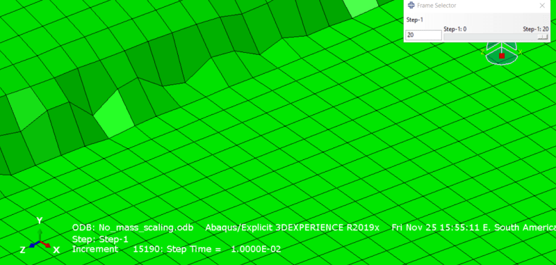
Figure_2_u0dieu.png


I’ve tried different parameters to improve the quality, such as: refining the mesh of the blank, refining the mesh of the punch, rounding sharp corners, reducing mass scaling and time scaling, changing the hourglass control method, choosing different contact approach (general contact and contact pairs), removing friction or inserting a maximum shear stress, but nothing seemed to work efficient.
Any suggestion on what I should try?
Below is some information about my model:
- Dynamic Explicit Analyses;
- ALE activated with different frequencies and sweep;
- Rigid punch;
- Deformable blank with hexaedral elements and reduced integration;
- Hourglass control: Enhanced or Default;
 
Replies continue below

Recommended for you

You may need a very fine mesh to capture this properly. Check the article "Finite element design procedure for correcting the coining die profiles" by P. Alexandrino et al.
 
Tks, FEA way.
Naturally, refining the mesh will help, but I don’t think it is only that.
I generated a simpler model to analyze the mesh faster, and when I double the number of elements the changes are not significant in the appearance of the coin.
The figures below show the simpler model with a relief height of 0.2mm. The elements have an average minimum edge length of 0.0183mm, and shortest edge of 0.00774mm.

Figure_5_lj2wbx.png
Figure_4_cb2lye.png

I could refine even more, but it would be an excessive fine mesh for all the other analyzes that I intend to do, considering that I’m getting similar contour plots for strain and stress. I will compare latter the Force x Displacement curve with an experiment too.
Do you think is happening an hourglass effect due a local bending? Or maybe a contact issue? Or even something that I could improve with Light Options settings? Because if you pay attention in the second figure with all edges visible you will see that the effect of the distorted elements is less apparent. Rotating the model the bright spots change too.

Tks again.
 
Maybe you could refine the mesh more locally - in regions where relief connects to the field. But some small inaccuracies might be unavoidable due to the nature of discretization and the shape of the finite elements being used.
 
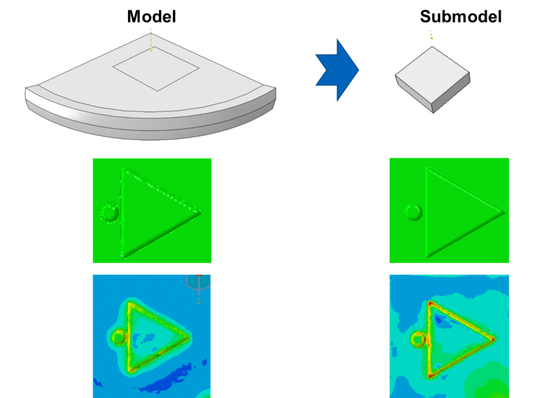
Is it possible to use Submodels to analyze some specific regions in contact problems like that? I'm trying to make a submodel including only the triangle geometry in order to check stress concentration with high accuracy using a fine mesh. The image below shows the stress distribution for the model and submodel.
Imagem1_fgmd6h.png


This procedure can be applied for contact problems in metal forming?
Tks
 
Node-based submodeling is quite versatile, it can be used for analyses involving contact and those performed in Abaqus/Explicit. Its limitations are listed in the documentation.
 
Hi, based on my experience, some times some strange things could happen visually if you don't scale back the auto-compute scale factor set to 1 after simulation , just personal opinion.
 
Thank you both.
I'm a beginner in submodelling. So I would like to share some settings that I'm using in order to see your opinion.

In the Global Model (the 1/4 part of the blank showed in the previous image) there is a boundary condition (BC) related to the vertical displacement (axis y) of the die to do the microforming process in the blank.
In the Submodel (the small paralelepiped in the image) I kept all parts (blank and die) in the assembly, and applied the same vertical displacement as a BC.
For the driven region of the submodel I insert 1 and 3 as x-axis and z-axis degrees of freedom that will be interpolated from the Global Model, and keep the DOF 2 out, considering that I'm already using a BC for the y-axis.
Is it seems right?

Tks again.
 
Yes, it should be correct but I would set that second DOF to driven too. Especially since it's not applied to the faces of the cut in the original model but probably to the top surface only. Regarding BCs, you can find some tips in the documentation chapter Analysis --> Analysis Techniques --> Modeling Abstractions --> Submodeling --> Node-Based Submodeling (paragraph Boundary Conditions).
 
Status
Not open for further replies.

Part and Inventory Search

Sponsor